Ostium stent system

a stent and ostium technology, applied in the field of medical devices, can solve problems such as weld cracking

a stent and ostium technology, applied in the field of medical devices, can solve problems such as weld cracking

US20050154447A1Inactive Publication Date: 2005-07-14MEDTRONIC VASCULAR INC

Image

  • Ostium stent system
  • Ostium stent system
  • Ostium stent system

Examples


Embodiment Construction

[0032] A preferred embodiment of the present invention is now described with reference to the figures, where like reference numbers indicate identical or functionally similar elements. Also in the figures, the left most digit of each reference number corresponds to the figure in which the reference number is first used. While specific configurations and arrangements are discussed, it should be understood that this is done for illustrative purposes only. A person skilled in the relevant art will recognize that other configurations and arrangements can be used without departing from the spirit and scope of the invention.

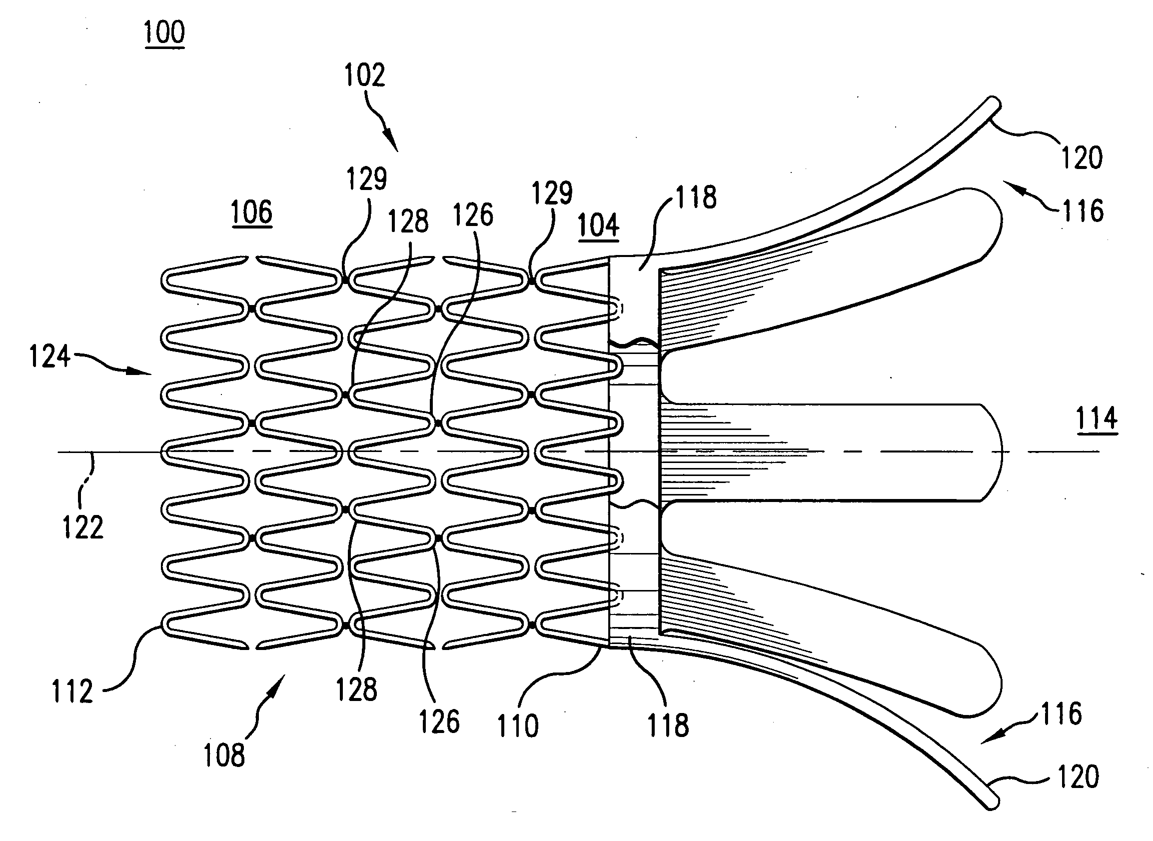
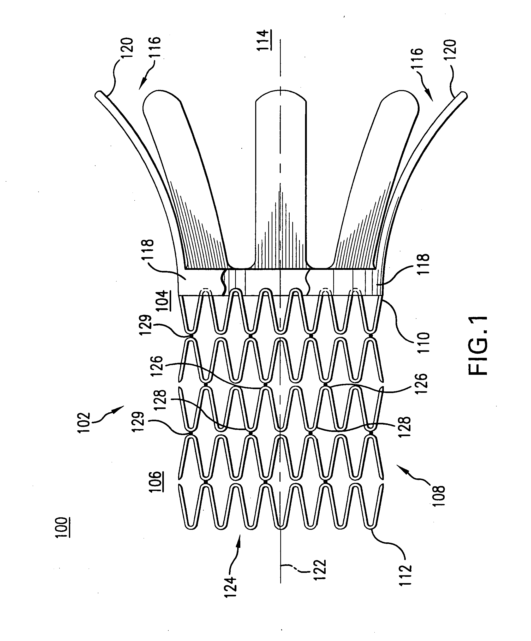
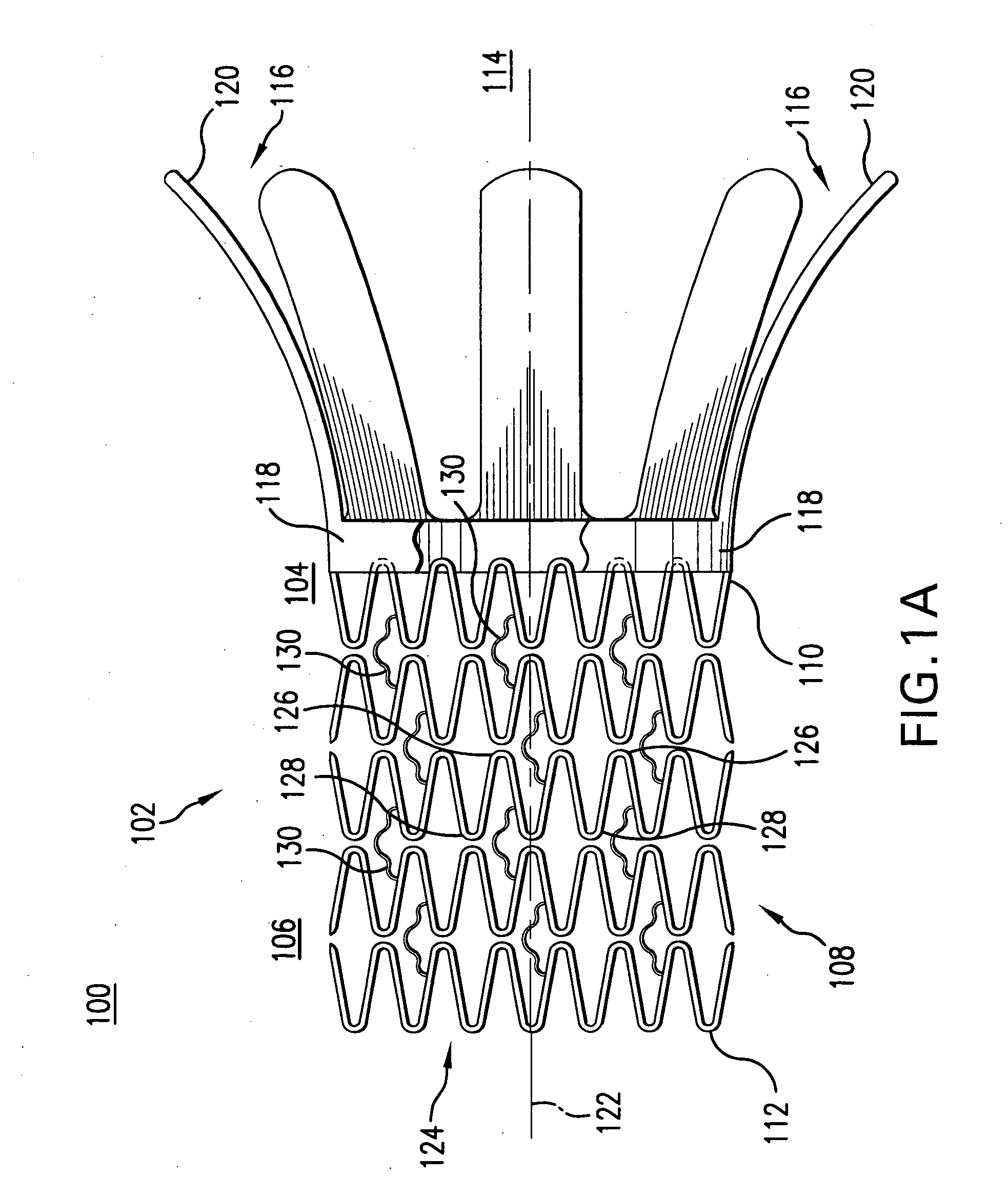
[0033] Referring to FIG. 1, an embodiment of an ostium stent system 100 of the present invention is shown. Ostium stent system 100 comprises a stent. 102, having a tubular body 108 at a distal portion 106 of stent 102 and a flaring portion 114 at a proximal portion 104 of stent 102. FIG. 1 shows a side view of ostium stent system 100 with flaring portion 114 in an exp...


PUM


Abstract

An ostium stent system includes a stent having a tubular body at the distal portion of the stent and a flaring portion at the proximal portion of the stent. A restraining structure that deploys the flaring portion covers only the proximal portion of the stent, providing a low profile for smooth delivery of the stent to the treatment site. The flaring portion comprises at least one flaring member which each comprise a short segment and a long segment. In an unexpanded configuration, each short and long segment are parallel to a longitudinal axis of the tubular body. When the flaring portion is deployed, each short segment remains parallel while each long segment becomes perpendicular to the longitudinal axis of the tubular body. The short segments therefore absorb the radial force resulting from deployment of the long segments and thereby prevent the stent from lifting off the balloon.

Description

BACKGROUND OF THE INVENTION [0001] 1. Field of the Invention [0002] The field of this invention generally relates to a medical device, and more particularly to an expandable stent positioned at an ostium for treatment of stenosis. [0003] 2. Background Art [0004] A wide range of medical treatments have been previously developed using “endoluminal prostheses,” which is herein intended to mean medical devices which are adapted for temporary or permanent implantation within a body lumen. Examples of lumens in which endoluminal prostheses may be implanted include, without limitation: arteries, veins, gastrointestinal tract, biliary tract, urethra, trachea, hepatic shunts, and fallopian tubes. Various types of endoluminal prostheses have been developed, each providing a uniquely beneficial structure to modify the mechanics of the targeted luminal wall. [0005] Various stent designs are known in the art for providing radial support to wall tissue, which form the various lumens within the bo...

Claims


Application Information

Patent Timeline
14 Jul 2005
Publication
US20050154447A1
IPC
A61B17/11; A61F2/82; A61F2/86; A61F2/90
CPC
A61F2/848; A61F2/86; A61F2/90; A61F2/915; A61F2230/0078; A61F2002/821; A61F2220/0058; A61F2230/005
Inventors
GOSHGARIAN, JUSTIN