
Control apparatus for internal combustion engine

a control apparatus and internal combustion engine technology, applied in the direction of electric control, combustion-air/fuel-air treatment, instruments, etc., can solve the problems of reduced learning precision of vapor concentration, difficult to determine, and reduced air/fuel ratio change, so as to prevent useless fuel consumption and efficiently perform the effect of increasing the amount of fuel

Inactive Publication Date: 2005-07-14
TOYOTA JIDOSHA KK
View PDF3 Cites 6 Cited by
  • Summary
  • Abstract
  • Description
  • Claims
  • Application Information

AI Technical Summary

Benefits of technology

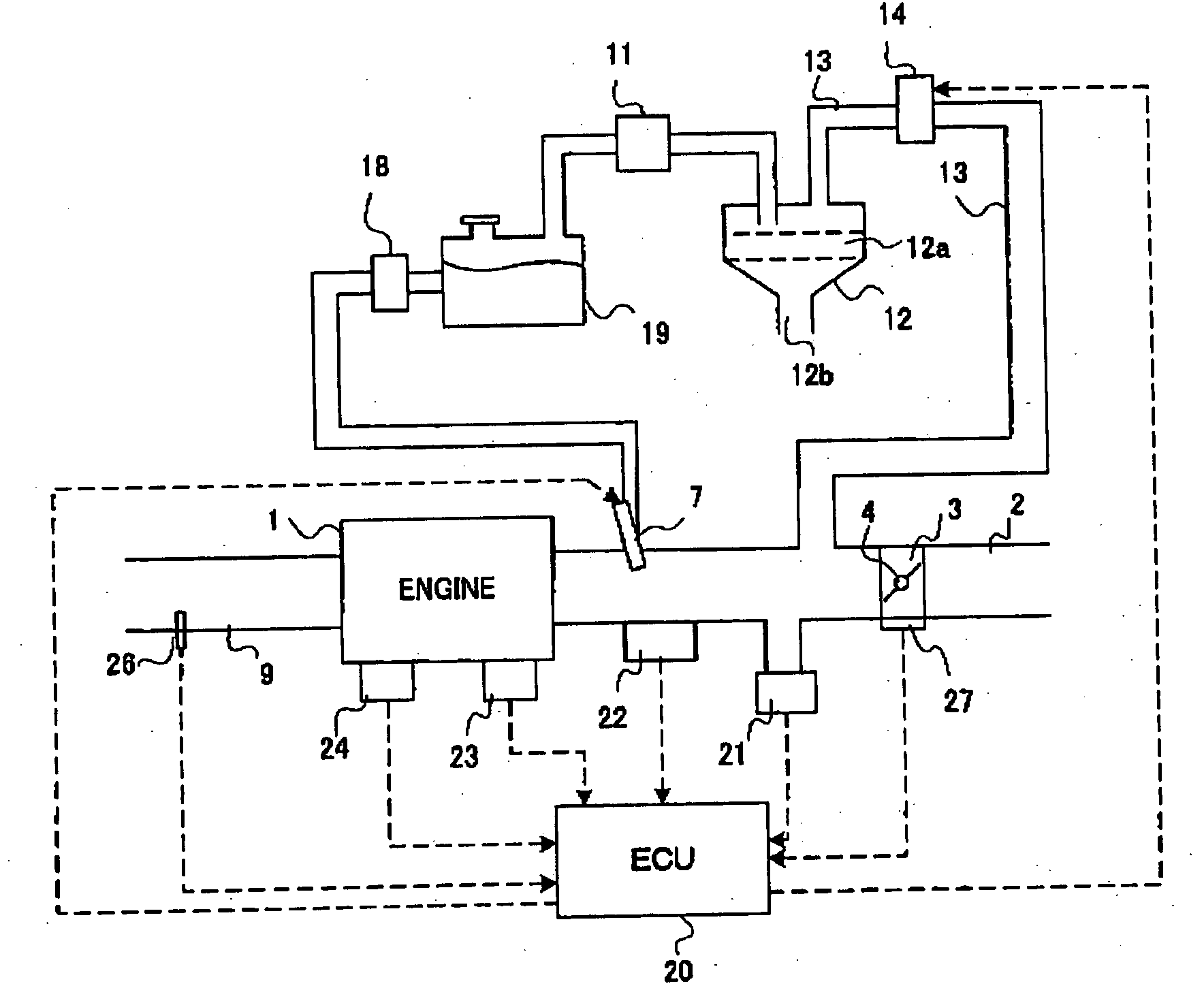
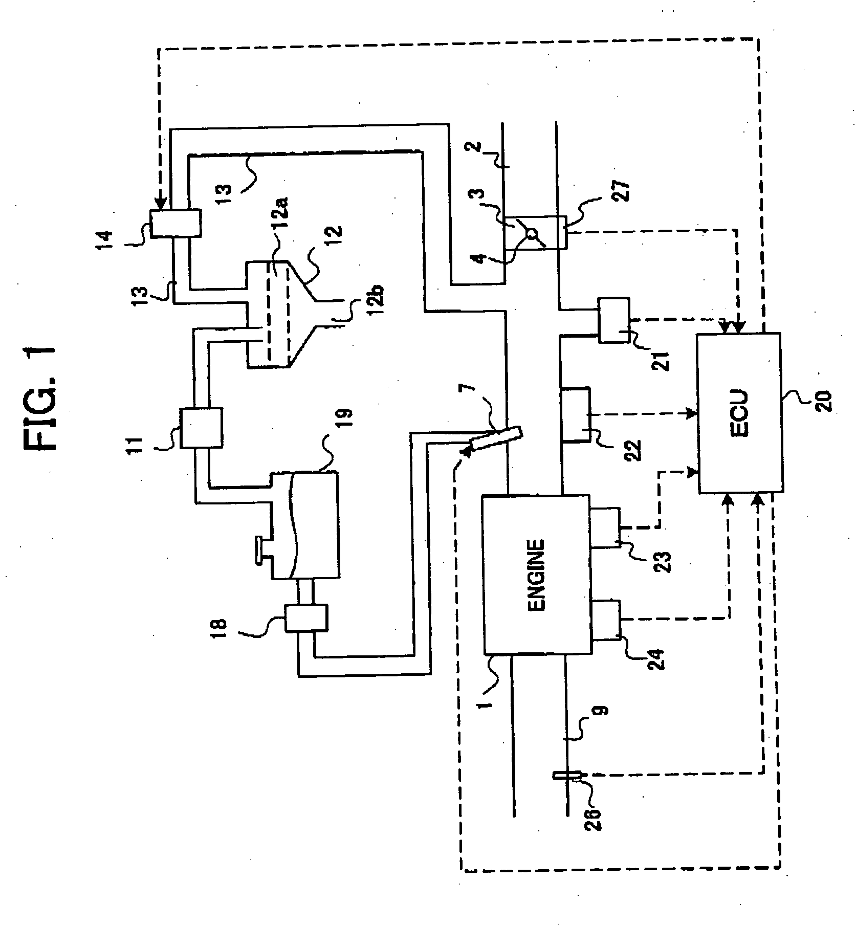
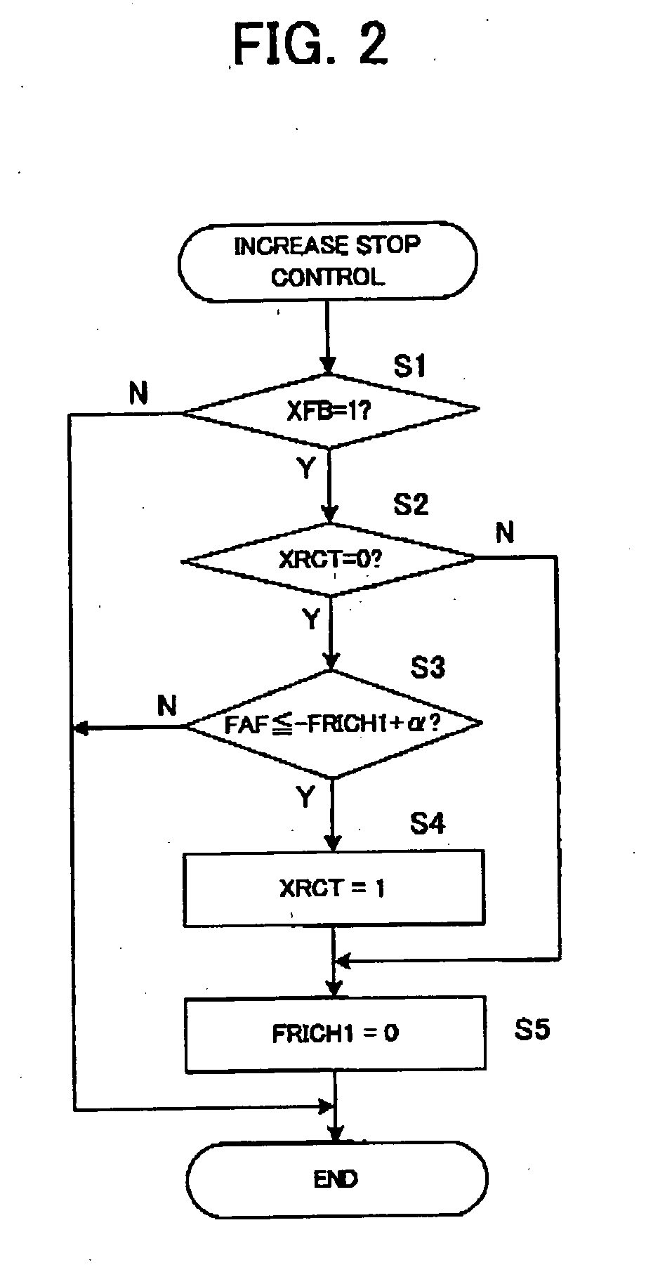
The present invention provides a control apparatus for an internal combustion engine that prevents unnecessary consumption of fuel by efficiently performing increase of fuel injection amount and executing purge control early. The control apparatus includes an increasing unit that increases fuel injection amount under predetermined conditions, an air / fuel ratio feedback control unit that controls fuel injection amount based on an output of an oxygen concentration sensor, and a control unit that decreases the increase amount of fuel injection amount when the air / fuel ratio feedback control unit corrects the increase amount. The control apparatus also includes a purge control unit that executes purge of a canister immediately after the control apparatus decreases the increase amount of fuel injection amount. The determination of whether the increase amount of fuel injection amount by the increasing unit is corrected or not is performed after a predetermined time has elapsed. The control apparatus can also decrease the increase amount of fuel injection amount by the increasing unit when the purge control is executed.

Problems solved by technology

However, when the fuel injection amount is increased, it is difficult to determine whether the change in the air / fuel ratio calculated by utilizing the oxygen concentration sensor is caused by the increase of the fuel injection amount, or by purge, and therefore, learning precision of the vapor concentration is reduced.
On the other hand, when the canister purge is not performed while the fuel injection amount is being increased at cold time after the start of the engine or the like, there arises the problem that the purge cannot be executed early at the cold time of the engine.

Method used


Image

  • Control apparatus for internal combustion engine
  • Control apparatus for internal combustion engine
  • Control apparatus for internal combustion engine

Examples


first embodiment

[0050] Next, a first embodiment of the control apparatus for the internal combustion engine of the present invention will be explained. The first embodiment relates to the control in case of increasing fuel injection amount at the cold time (when the engine is not sufficiently warmed) at the engine starting time and the like, for example. At the cold time, evaporation of the fuel is insufficient even when a predetermined amount of fuel is injected from the fuel injection valve 7, the fuel adheres to an inner wall and the like of the intake pipe and the combustion chamber, and the amount of the fuel which does not contribute to combustion in the combustion chamber becomes large. Therefore, at the engine starting time and at the cold time, the fuel injection amount is increased. However, when the fuel is increased when the purge control of the aforementioned canister is performed, an error occurs to learning of the vapor concentration by purge, and precision is lowered. Therefore, in ...

second embodiment

[0068] Next, a second embodiment of the present invention will be explained. A first example to a third example which will be explained hereinafter are all predicated on the control of the first embodiment.

FIRST EXAMPLE

[0069] The first example of the second embodiment performs determination of whether or not the feedback correction amount FAF reaches the correction amount corresponding to the fuel increase amount FRICH1 after a predetermined time period elapses from the start of the feedback control. A flow chart of the control in the first example is shown in FIG. 6, and a timing chart is shown in FIG. 7.

[0070] More specifically, the ECU 20 counts the elapsed time after the start of the feedback control. This count value is set as “CRCT”. The count value corresponding to the predetermined time is set as “KCRCT”. In FIG. 7, the ECU 20 starts the feedback control at the time t1, and thereby, the count value CRCT increases. After the time t2 when the count value CRCT reaches the pr...

third example

[0081] A third example of the second embodiment does not perform the determination of whether the feedback control amount FAF reaches the correction amount corresponding to the fuel increase amount or not when the load variation of the engine is large. When the load variation of the engine is large at the accelerating time of the vehicle, decelerating time and the like, the amount of fuel introduced into the combustion chamber becomes unstable, and therefore an error easily occurs to the determination of the increase stopping time. Therefore, when the load variation of the engine is large, the determination of whether the feedback control amount FAF reaches the correction amount corresponding to the fuel increase amount or not, namely, the determination of the increase stopping time is not performed. The load variation of the engine can be determined based on, for example, the variation of the negative pressure inside the intake pipe detected by the pressure sensor 21, the variation...


PUM


Abstract

The control apparatus for the internal combustion engine increases a fuel injection a mount under predetermined conditions, such as after the start of the internal combustion engine, at cold time, at acceleration requiring time, at gear shifting time from a neutral to a D-range, for example. When the fuel injection amount is increased during execution of air / fuel ratio feedback control, the feedback control follows the increase amount, and executes correction corresponding to the increase amount. Then, at the point of time when the correction corresponding to the increase amount is completed, the increase of the fuel injection amount is stopped quickly. Thereby, the increase of the fuel injection amount is not continued unnecessarily, and therefore useless consumption of the fuel can be suppressed. Also, it becomes possible to start other controls early by finishing increase quickly. For example, when the canister purge is executed during the increase of the fuel injection amount, it is difficult to distinguish an evaporated fuel amount by purge and an increase amount by the fuel increase, and learning precision of a vapor concentration is lowered. Therefore, purge is not performed during the increase of the fuel injection amount, and the purge control is performed after the fuel increase is stopped quickly, whereby it becomes possible to start purge control early.

Description

BACKGROUND OF THE INVENTION [0001] 1. Field of the Invention [0002] The present invention relates to increase control and increase stop control of a fuel injection amount of an internal combustion engine. [0003] 2. Description of the Related Art [0004] In an internal combustion engine, so-called air / fuel ratio feedback control is carried out to keep the air / fuel ratio at a target air / fuel ratio. More specifically, an oxygen concentration in exhaust gas is detected by an oxygen concentration sensor provided in an exhaust system of the internal combustion engine, and the air / fuel ratio is calculated based on the detected oxygen ratio and the fuel injection amount. A feedback correction amount is determined to eliminate a deviation of the calculated air / fuel ratio and the target air / fuel ratio, thereby performing feedback control of the fuel injection amount. [0005] In an automobile, a canister which adsorbs evaporated fuel in a fuel tank is provided, and canister purge (hereinafter, s...

Claims


Application Information

Patent Timeline
Patent Type & Authority Applications(United States)
IPC IPC(8): F02D41/00F02D41/02F02D41/04F02M25/08F02D41/06F02D41/10F02D41/12F02D41/14F02D45/00G06F7/00G06F17/00
CPCF02D41/0032F02D41/023F02D41/047F02D41/1473F02D41/10F02D41/1454F02D41/06
Inventor OSANAI, AKINORI
Owner TOYOTA JIDOSHA KK
Learn More