Rotational speed and position detector for supercharger compressor

a supercharger compressor and detector technology, applied in the direction of internal combustion piston engines, machines/engines, combustion engines, etc., can solve the problems of high manufacturing cost and certain weight imbalance in the compressor blade, and achieve the effect of low cost and accurate detection

Inactive Publication Date: 2005-07-21
DENSO CORP
View PDF13 Cites 45 Cited by
  • Summary
  • Abstract
  • Description
  • Claims
  • Application Information

AI Technical Summary

Benefits of technology

[0009] The present invention has been made in view of the above-mentioned problems, and an object of the present invention is to provide an improved device for detecting ...

Problems solved by technology

In the detecting device disclosed in JP-A-5-79340, however, the following problems are involved.
Since the permanent magnet is embedded in the rotating compressor blade, a certain weight unbalance ap...

Method used


Image

  • Rotational speed and position detector for supercharger compressor
  • Rotational speed and position detector for supercharger compressor
  • Rotational speed and position detector for supercharger compressor

Examples


Embodiment Construction

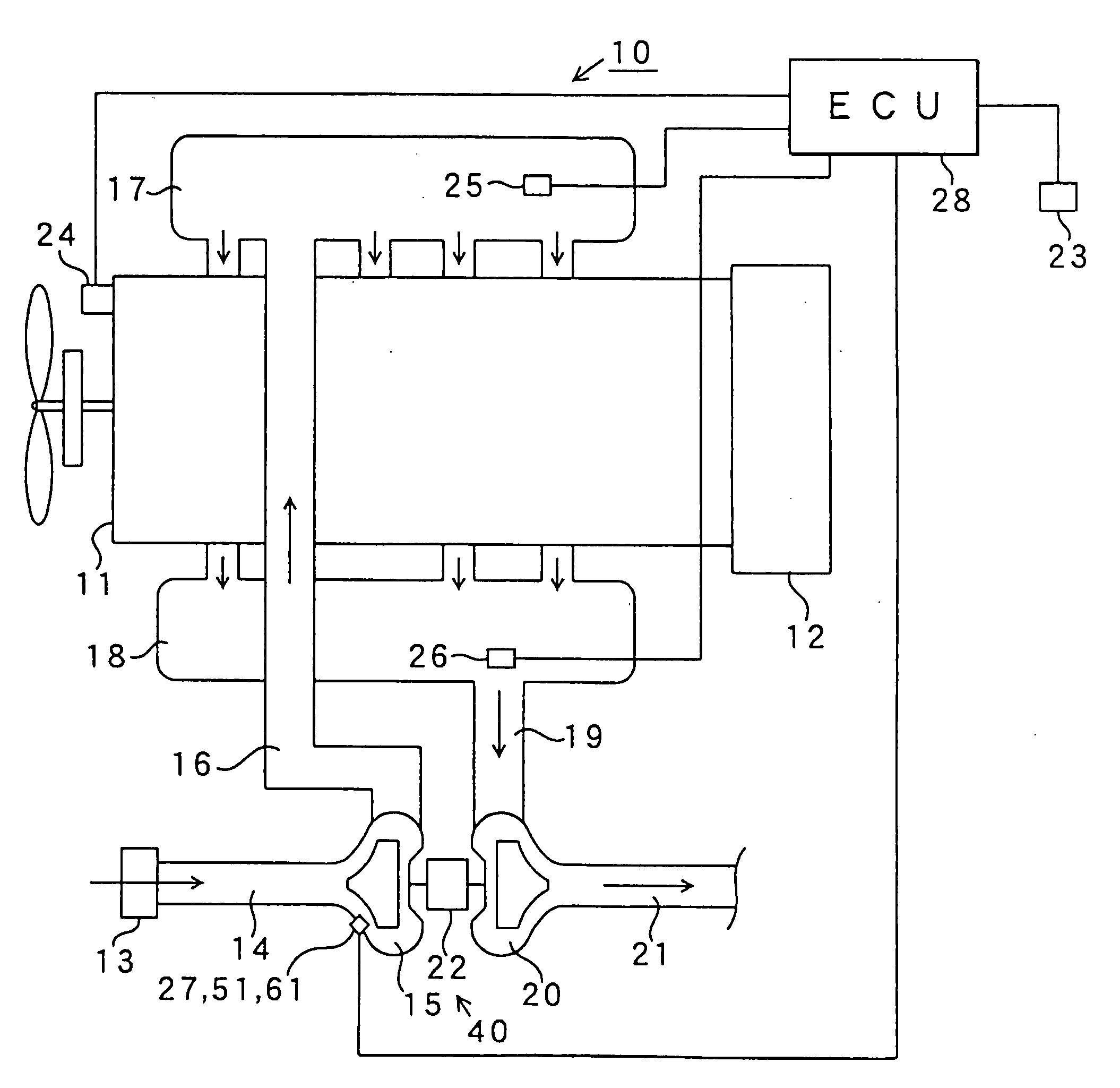
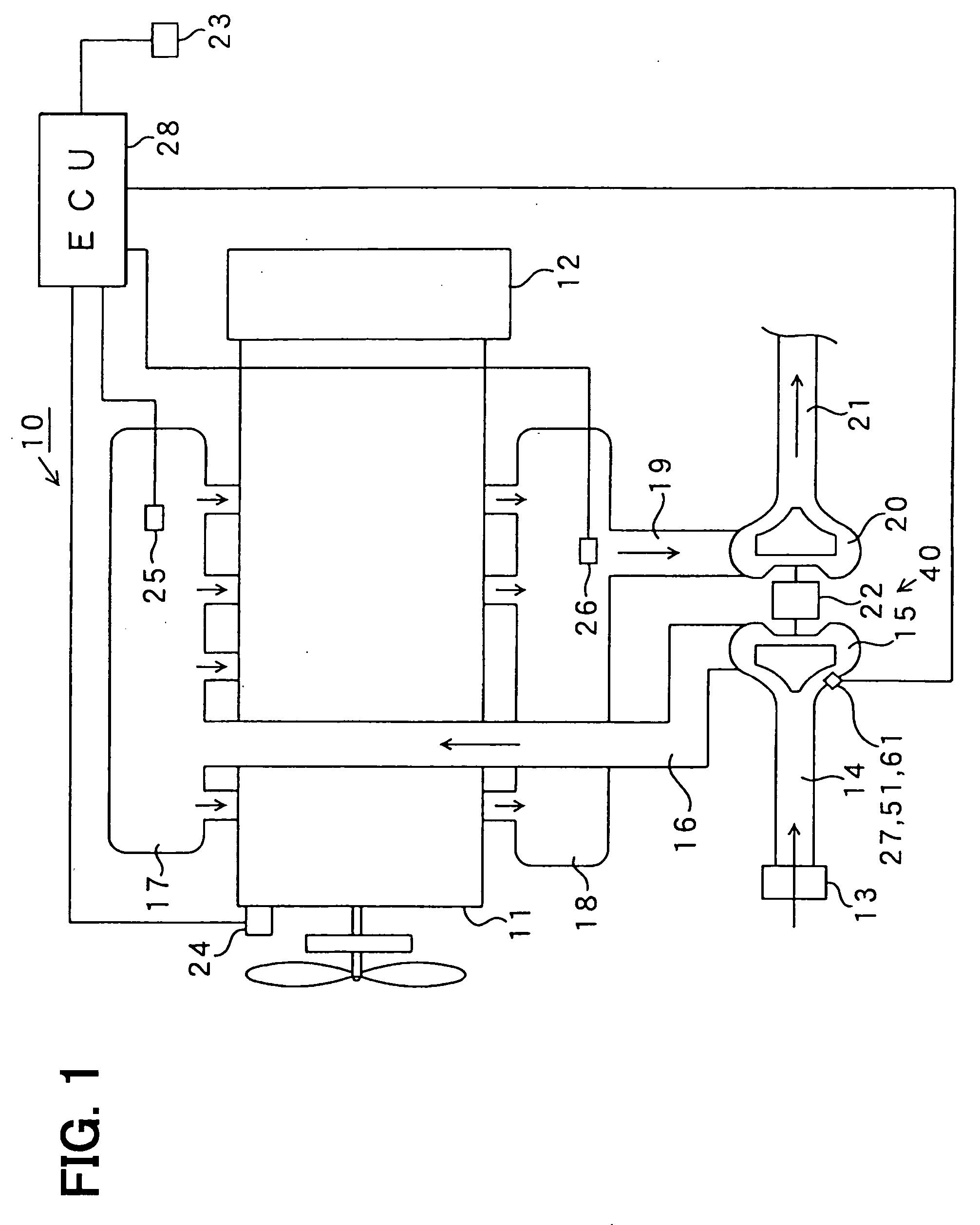
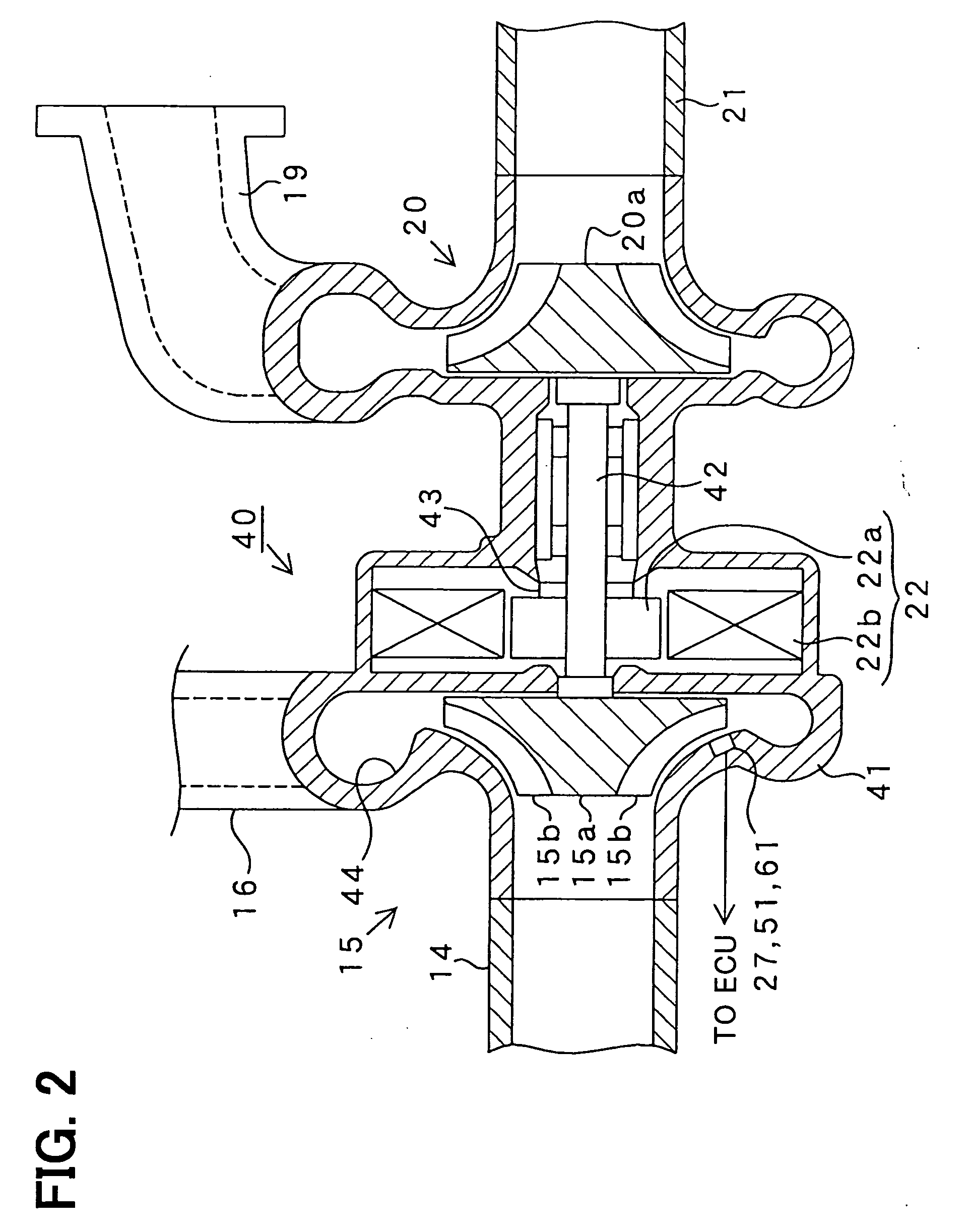
[0022] A first embodiment of the present invention will be described with reference to FIGS. 1 and 2. An engine system 10 shown in FIG. 1 has a supercharger which is referred to as a motor-assisted turbocharger. The engine system 10 includes an internal combustion engine 11, a flywheel housing 12, an air cleaner 13, an intake pipe 14, a compressor 15, a connecting pipe 16, an intake manifold 17, an exhaust manifold 18, another connecting pipe 19, a turbine 20, an exhaust pipe 21, a rotary electric machine 22, an accelerator sensor 23, an engine speed sensor 24, a pressure sensor 25, another pressure sensor 26, a magnetic sensor 27, and an electronic control unit 28 for controlling operation of the engine.

[0023] The accelerator sensor 23 detects an opening degree of an accelerator which is operated by a driver. The engine speed sensor 24 detects a rotational speed of a crankshaft (not shown) of the engine 11. The pressure sensor 25 detects a pressure in the intake manifold, i.e., an...


PUM


Abstract

A motor-assisted turbocharger is composed of a turbine driven by energy of exhaust gas, a compressor rotated by the turbine and a rotary electric machine for assisting rotation of the compressor. The turbine, the compressor blade and the rotary electric machine are connected to each other by a common rotating shaft. The compressor blade made of a material including a magnetic material faces an inner surface of a housing in which a magnetic sensor is embedded. A magnetic field in an air gap between the compressor blade and the magnetic sensor changes according to rotation of the compressor blade. The magnetic sensor detects changes in the magnetic field to thereby detect the rotational speed of the compressor blade. In place of the magnetic field, other physical amounts in the air gap, such as pressure, sound frequencies, capacitance or the like may be used for detecting the rotational speed.

Description

CROSS-REFERENCE TO RELATED APPLICATION [0001] This application is based upon and claims benefit of priority of Japanese Patent Application No. 2004-8256 filed on Jan. 15, 2004, the content of which is incorporated herein by reference. BACKGROUND OF THE INVENTION [0002] 1. Field of the Invention [0003] The present invention relates to a rotational speed detector, and more particularly to a device for detecting a rotational speed and a rotational position of a rotating blade of a supercharger compressor for used in an internal combustion engine. [0004] 2. Description of Related Art [0005] A supercharger is used for compressing air to be supplied to an intake manifold of an internal combustion engine to obtain a higher output of the engine. A compressor of the supercharger is driven by various methods. For example, the compressor is rotated by a turbine driven by energy of exhaust gas. The compressor may be directly driven by a rotational torque of a crankshaft of an engine, or by an i...

Claims


Application Information

Patent Timeline
IPC IPC(8): F02B39/00F02B33/44F02B37/14F02B39/10
CPCF02B37/14Y02T10/144F02B39/10Y02T10/12
Inventor SUGIURA, MAKIKOTOYODA, INAOYAMADA, TOSHITAKA
Owner DENSO CORP
Why Eureka
Try Eureka