
Vibration sensor and method for monitoring the condition of rotating components and bearings

a technology of vibration sensor and bearing, which is applied in the field of vibration sensor, can solve the problems of not using expert know-how for reliable bearing diagnosis and bearing damage detection, and achieve the effect of easy reliable monitoring of the state of rotating components and bearings

Active Publication Date: 2005-07-21
I FOR T
View PDF13 Cites 38 Cited by
  • Summary
  • Abstract
  • Description
  • Claims
  • Application Information

AI Technical Summary

Benefits of technology

[0009] Therefore, an object of this invention is to embody and develop an exemplary vibration sensor and process, such that reliable monitoring of the state of rotating components and bearings can be done easily, and, thus, economically, and wherein the vibration sensor is to be operated in a simple a manner as possible.

Problems solved by technology

By converting the plurality of measured signals using signal analysis and the diagnosis algorithm in a simple state value, expensive expert know-how for reliable bearing diagnosis and for detection of bearing damage need not be employed.

Method used


Image

  • Vibration sensor and method for monitoring the condition of rotating components and bearings
  • Vibration sensor and method for monitoring the condition of rotating components and bearings
  • Vibration sensor and method for monitoring the condition of rotating components and bearings

Examples


Embodiment Construction

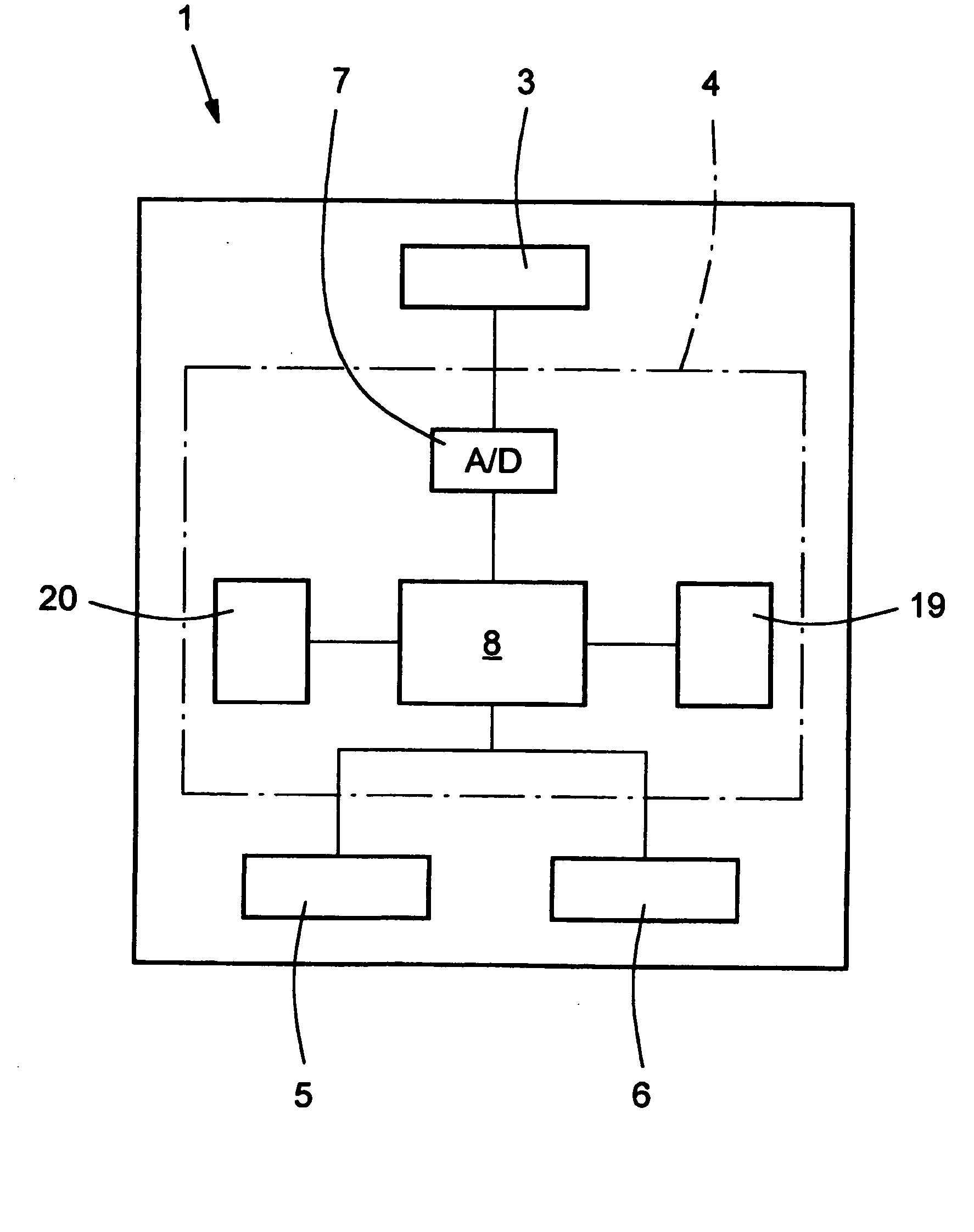
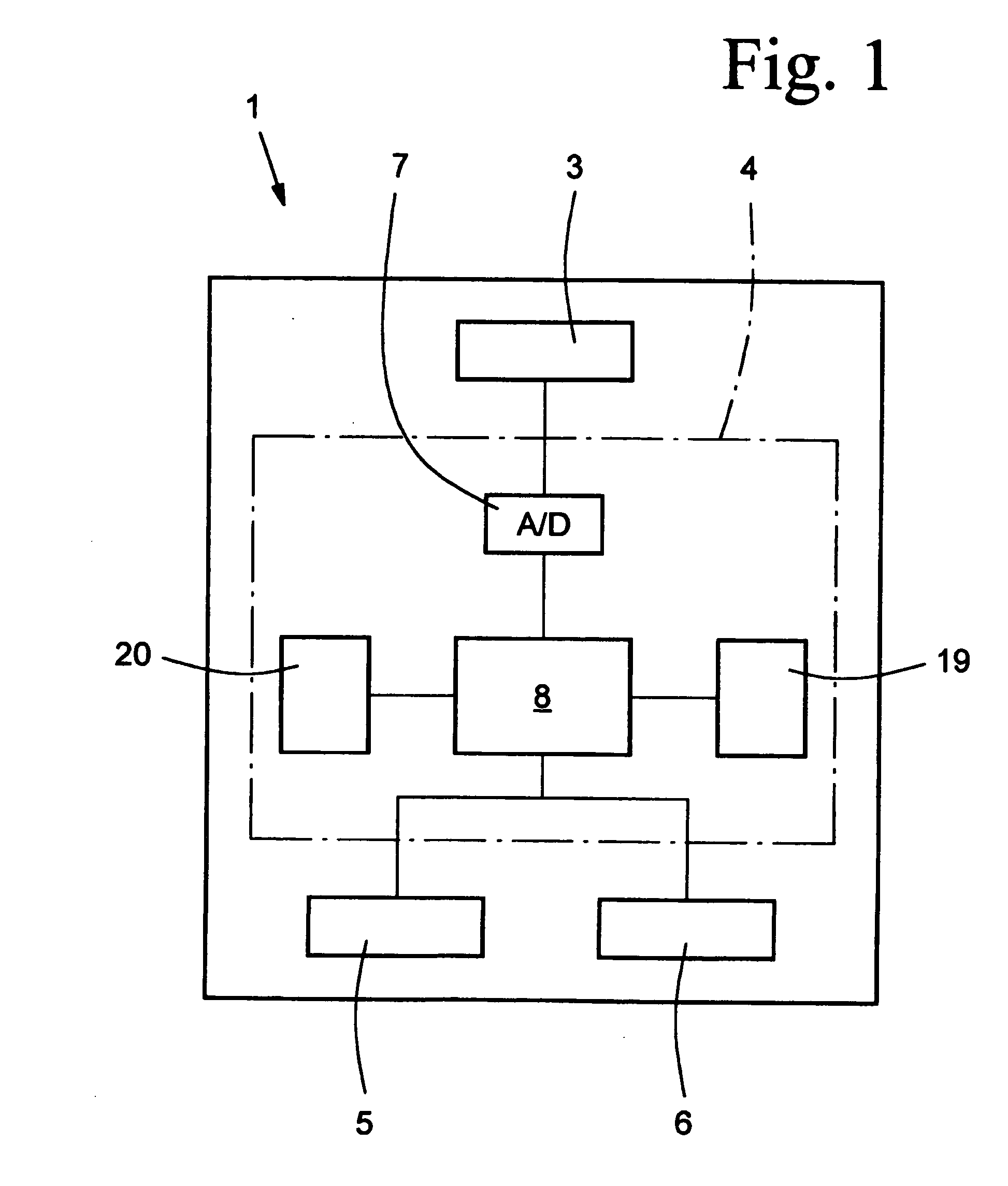
[0039] The figures show a vibration sensor 1 with a plastic or aluminum housing 2, with a sensor element 3, which is located in the housing 2, and with evaluation electronics 4, and with two interfaces 5, 6, and which is shown schematically in FIG. 1. The evaluation electronics 4, includes an analog-to-digital converter 7, which is connected to the sensor element 3, and a signal conditioning means 8, which is connected to the analog-to-digital converter 7. The signal conditioning means 8 is generally implemented by a microprocessor, which can form the evaluation electronics 4, such that the analog-to-digital converter 7 is integrated in the microprocessor.

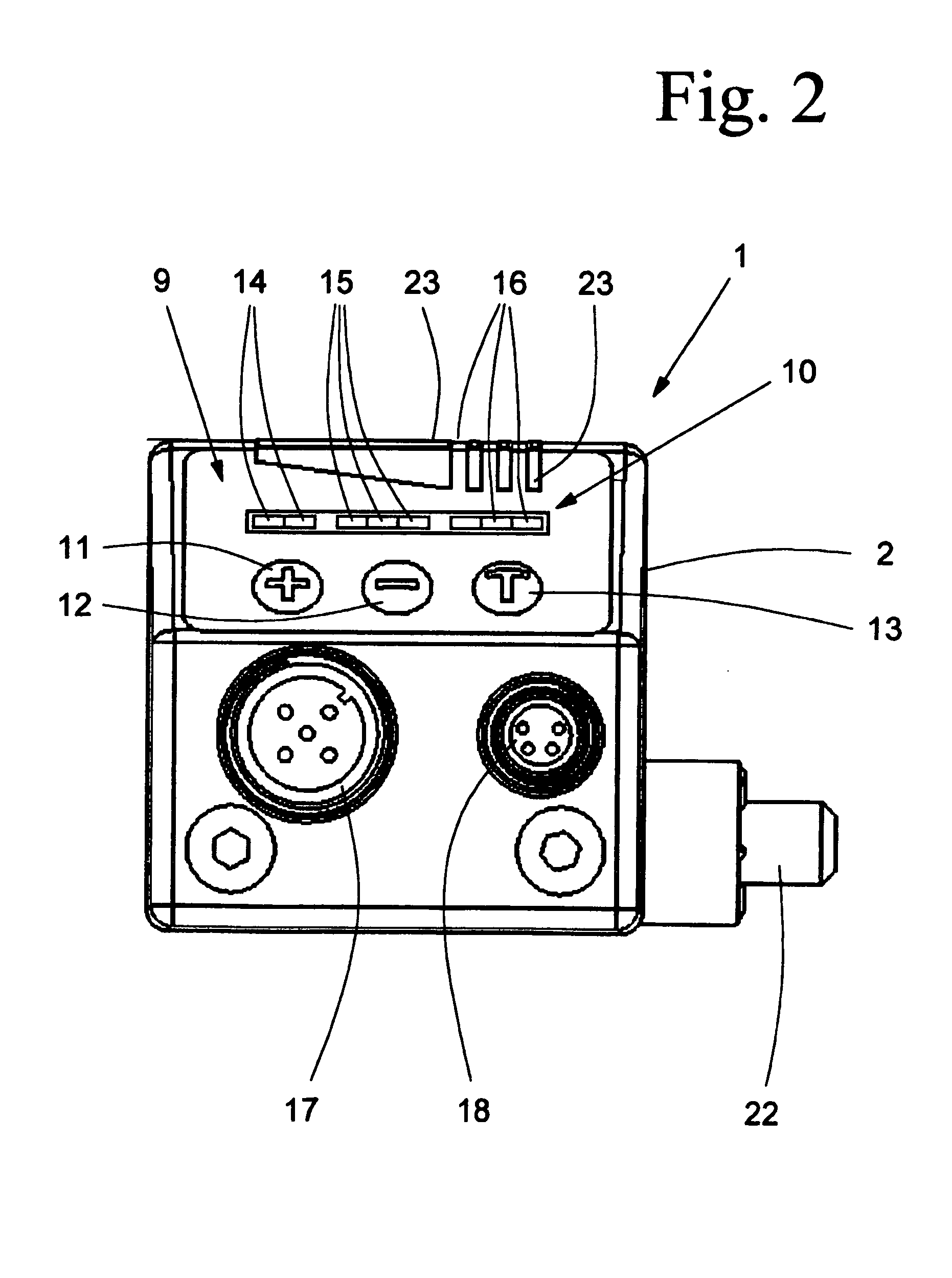
[0040] As can be recognized from FIG. 2, the vibration sensor 1 has a display means 9 with a display 10 and three control elements 11, 12, 13. The control elements 11 and 12 are used for setting boundary values, wherein when these boundary values are reached, a pre-alarm or main alarm is triggered by the vibration sensor 1. Moreov...


PUM

PropertyMeasurementUnit
angleaaaaaaaaaa
current rpmaaaaaaaaaa
edge lengthaaaaaaaaaa

Abstract

A vibration sensor (1) for monitoring the state of rotating components or bearings, includes a housing (2), a sensor element (3), evaluation electronics (4), and at least one interface (5, 6). With the vibration sensor (1), reliable monitoring of the state of rotating components and bearings can be done easily and economically, and in addition the vibration sensor can be easily operated. The evaluation electronics (4) has an analog-to-digital converter (7), and a signal conditioning means (8) having a plurality of signals, which have been acquired by the sensor element (3), and which are converted into a state value using signal analysis and a diagnosis algorithm.

Description

BACKGROUND OF THE INVENTION [0001] 1. Field of the Invention [0002] The invention relates to a vibration sensor for monitoring the state of rotating components or bearings, with a sensor element, with evaluation electronics and with at least one interface. In addition the invention also relates to a process for monitoring the state of rotating components or bearings with a vibration sensor which has a sensor element and evaluation electronics. [0003] 2. Description of Related Art [0004] In mechanical engineering and plant engineering there are a host of machines and systems which each have rotating components, generally a shaft. The shaft is supported via a bearing, especially a roller bearing, in the stationary housing of the machine or equipment. Depending on the embodiment, the inside ring or the outside ring of the bearing being movably arranged, while then accordingly the inside ring or the outside ring is supported to be stationary. Problem-free serviceability of the bearing, ...

Claims


Application Information

Patent Timeline
Patent Type & Authority Applications(United States)
IPC IPC(8): G01HG01H1/00G01N29/00
CPCG01M13/045
Inventor GRIESSLER, ERICHHERBERHOLZ, PETERKATHAN, BENNOMAY, THOMASBAUER, CHRISTIANDANITSCHEK, MICHAEL
Owner I FOR T
Learn More