Driver circuit for light emitting element

Inactive Publication Date: 2005-07-21
RENESAS ELECTRONICS CORP
View PDF9 Cites 24 Cited by
  • Summary
  • Abstract
  • Description
  • Claims
  • Application Information

AI Technical Summary

Benefits of technology

[0010] Accordingly, it is an object of the present invention to provide a driver circuit that makes it possible to reduce the size

Problems solved by technology

Since the gamma correction circuit 131 is necessary in this arrangement, however, not only is the circuitry large in size but an additional problem is a reduction of grayscales that can be expressed.
Consequently

Method used


Image

  • Driver circuit for light emitting element
  • Driver circuit for light emitting element
  • Driver circuit for light emitting element

Examples


Embodiment Construction

[0058] The present invention will be described below with reference to the accompanying drawings.

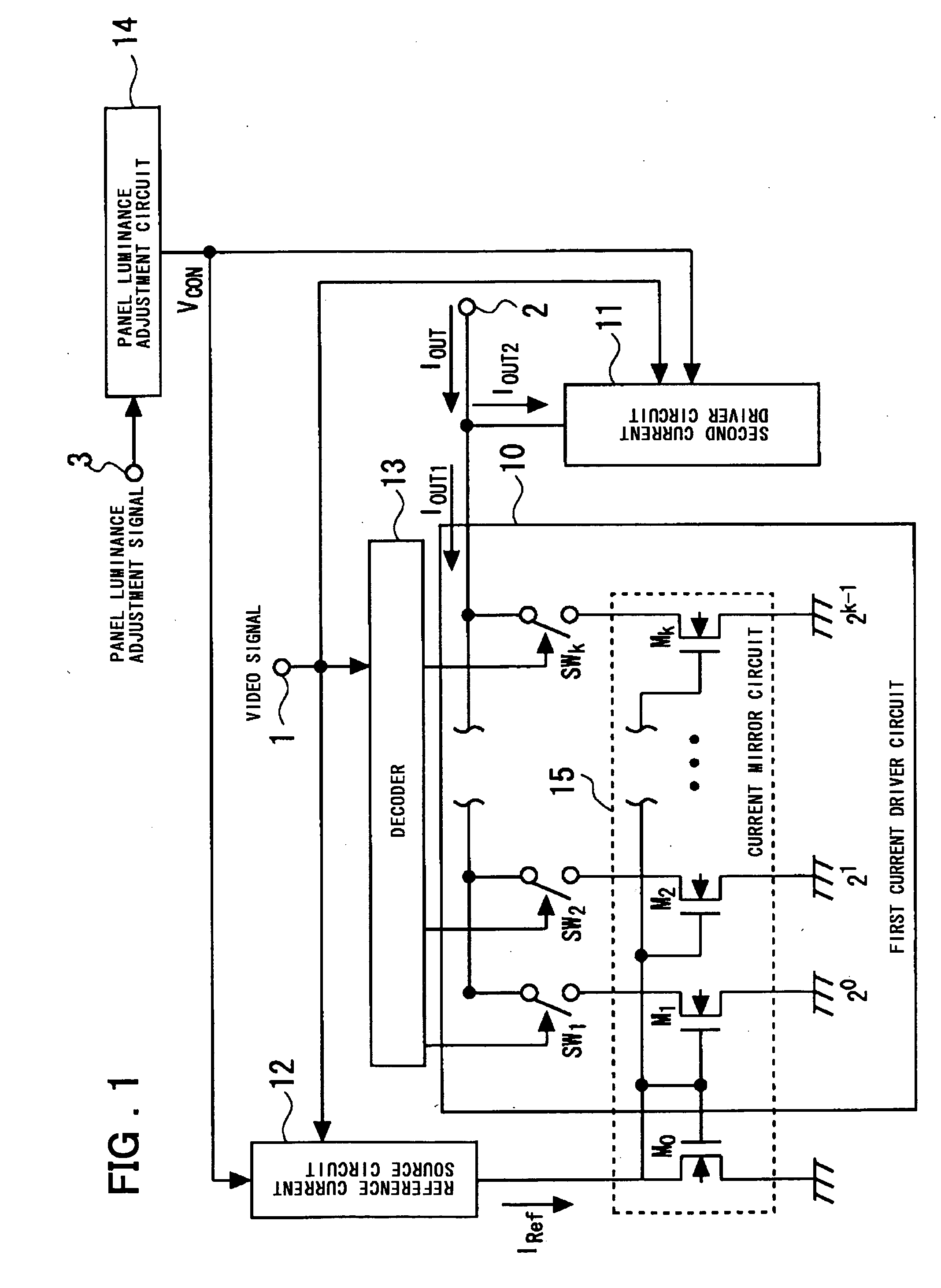
[0059] The overall structure of a display device according to an embodiment of the present invention will be described with reference to FIG. 24. The display device incorporates a gamma correction function in a display-element driver circuit 130 to which an input signal (video signal) is applied for driving current through a display element of a display panel. By virtue of this structure, the area of the circuitry and area of the chip when the device is integrated can be reduced in comparison with the conventional structure shown in FIGS. 26 and 27. A further characterizing feature is that the display-element driver circuit 130 supports 256 grayscale levels (represented by eight bits) and is capable of delivering a 256 grayscale input signal to a display element (panel) 133. A gamma correction circuit supporting 512 grayscale levels (represented by nine bits) and a display-element drive...


PUM


Abstract

Disclosed is a display driver that includes a first current driver circuit, a second current driver circuit and a reference current source circuit. The first current driver circuit, which has plural current sources the output current values of which are determined based on a reference current, and switch circuits for on/off controlling the current path between the plural current sources and the current output terminal based on video signal composed of plural bits. The first current driver circuit outputs a first output current conforming to the video signal. The second current driver circuit outputs the second output current conforming to the video signal, while the reference current source circuit variably controls the reference current based on the value of the video signal. A current that is the result of combining the first and second output currents from the first and second current driver circuits is output as an output current. An amount of change in the output current that corresponds to a change of one LSB of the video signal, is varied in accordance with the value of the video signal, the gamma characteristic is approximated by piece-wise linear approximation and the overall luminance of the display pane is variably controlled based on a control signal from a panel luminance adjustment circuit.

Description

FIELD OF THE INVENTION [0001] This invention relates to a driver circuit for a light-emitting element and to a display device. More particularly, the invention relates to a driver circuit and device that perform a gamma correction. BACKGROUND OF THE INVENTION [0002] An arrangement of the kind illustrated in FIG. 25 by way of example is known as an electroluminescent storage device (refer to the specification of Japanese Patent Kokai Publication No. JP-A-2-14868 pages 5 and 6, FIG. 2). As shown in FIG. 25, this conventional electroluminescent device includes an electroluminescent element 40; a plurality of memory cells 22 corresponding to the electroluminescent element 40; a current source 28 (a current mirror comprising transistors 26 and 27); current control means (transistors) 24, which correspond to the plurality of memory cells 22, connected to corresponding ones of the memory cells 22 and responsive to signals, which are held in the memory cells 22, for controlling current that...

Claims


Application Information

Patent Timeline
IPC IPC(8): G09G3/20H01L51/50G09G3/30G09G3/32G09G3/36H01L33/00H04N3/12H04N5/202H04N5/70H05B33/14H05B44/00
CPCG09G3/32G09G3/3283G09G3/3685G09G2320/0626G09G2320/0276G09G2320/0606G09G2310/027G09G3/30
Inventor YONEYAMA, TERUSAEKI, YUTAKA
Owner RENESAS ELECTRONICS CORP
Why Eureka
Try Eureka