Crytographic communication apparatus

a communication device and quantum cryptography technology, applied in the direction of coding theory basic assumptions, digital transmission, coding bounds, etc., can solve the problems that the device of authentication must be performed in classical communication, and the eavesdropper cannot always perform correct quantum demodulation. , the problem of a half (about 23)

Inactive Publication Date: 2005-07-21
MITSUBISHI ELECTRIC CORP
View PDF2 Cites 62 Cited by
  • Summary
  • Abstract
  • Description
  • Claims
  • Application Information

AI Technical Summary

Problems solved by technology

Generally, in the quantum transmitting step (S14), even if the device of the eavesdropper eavesdrops the transmitted qubit, the device of the eavesdropper cannot always perform correct quantum demodulation as the device of the eavesdropper does not know the base information which has been used for the quantum modulation.
In the conventional quantum cryptography communication device and communication method, there is a problem that the authentication must be performed in classical communication, using the secretly shared information which has been prepared in advance.
Further, there is a problem that the base exchange in which information on the quantum mod

Method used


Image

  • Crytographic communication apparatus
  • Crytographic communication apparatus
  • Crytographic communication apparatus

Examples


embodiment 1

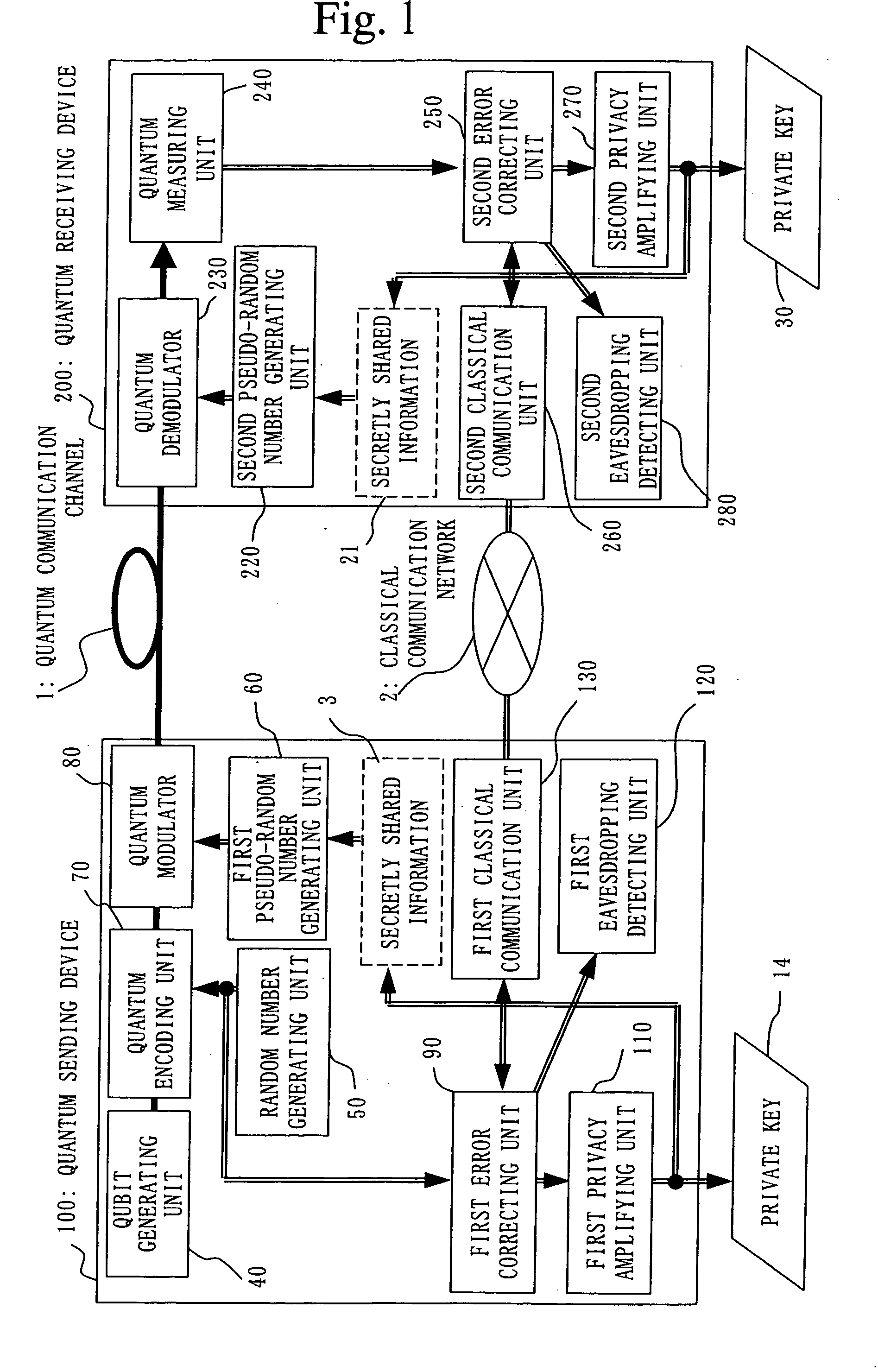
[0084]FIG. 1 shows a whole configuration chart of Embodiment 1.

[0085] In FIG. 1, the quantum sending device 100 and the quantum receiving device 200 are connected by the quantum cryptography communication channel 1 for transmitting a qubit from the quantum sending device 100 to the quantum receiving device 200.

[0086] The classical communication network 2 is a communication network which connects the quantum sending device and the quantum receiving device.

[0087] The secretly shared information 3 and the secretly shared information 21 are secret information which have been shared in advance between the quantum sending device and the quantum receiving device.

[0088] An internal configuration of the quantum sending device 100 will be explained.

[0089] A qubit generating unit 40 outputs a predefined qubit

|0>

periodically. Here, as the qubit, a polarization state of a photon, which is [0090] for qubit |0>, horizontal polarization state |H>, and for qubit |1>, vertical polarization sta...

embodiment 2

[0159] In this embodiment, an embodiment of adopting a phase state of a photon as a qubit and performing the quantum cryptography communication using a Mach-Zehnder interferometer is described.

[0160]FIG. 3 shows a whole configuration chart of Embodiment 2. A Mach-Zehnder interferometer 900 includes the qubit generating unit 40, a first phase modulator 81, a quantum communication channel 101, a quantum communication channel 102, the quantum measuring unit 240, and a second phase modulator 231. Difference in configuration from Embodiment 1 is the configuration of the qubit generating unit, the quantum encoding unit, the quantum modulator, the quantum communication channel, the quantum demodulator, and the quantum measuring unit.

[0161] Below, component parts which are different from Embodiment 1 are explained.

[0162] The qubit generating unit 40 includes a single-photon source 700, a beam-splitter 350, and a mirror 400.

[0163] A photon which has been output from the single-photon sou...

embodiment 3

[0183] In the above embodiments, the qubit generating unit has been provided in the quantum sending device 100. In this embodiment, the system can be realized also with a configuration where the qubit generating unit is provided in the quantum receiving device 200 (document 5: G. Ribordy, J.-D. Gautier, N. Gisin, O. Guinnard, H. Zbinden, “Automated “Plug & Play” Quantum Key Distribution,” Electronics Lett. 34, PP. 2116-2117, (1998)).

[0184]FIG. 4 shows a whole configuration chart of Embodiment 3. In this embodiment, as illustrated in FIG. 4, a forward path and a return path between the quantum sending device and the quantum receiving device are provided respectively as the quantum communication channels (a quantum communication channel in a forward path 105 and a quantum communication channel in a return path 106). However, it is also possible to realize a configuration in which an identical optical path is used as a forward path and a return path by using an optical path control un...


PUM


Abstract

A qubit generating unit 40 generates a qubit having a predetermined quantum state. A qubit encoding unit 70 performs quantum encoding of the generated qubit. A first pseudo-random number generating unit 60 generates a first pseudo-random number from secretly shared information 3 which has been secretly shared with the quantum receiving device 200 in advance. A quantum modulator 80 performs quantum modulation of the qubit on which quantum encoding has been performed based on the first pseudo-random number and sends the modulated qubit to the quantum receiving device 200. A second pseudo-random number generating unit 220 generates a second pseudo-random number from secretly shared information 21 which has been secretly shared with the above quantum sending device 100 in advance synchronously with generation of the above first pseudo-random number. A qubit demodulator 230 performs quantum demodulation of the qubit which has been received from the quantum demodulator 80 based on the second pseudo-random number.

Description

TECHNICAL FIELD [0001] This invention relates to a quantum cryptography communication device and a quantum cryptography communication method which share random number information while maintaining privacy by detecting an eavesdropper based on uncertainty principle in quantum mechanics. BACKGROUND ART [0002] A whole configuration chart in FIG. 5 illustrates conventional techniques represented by quantum cryptography which was first proposed by Bennett and Brassard in 1984 (Document 1: C. H. Bennett and G. Brassard, “Quantum Cryptography: Public Key Distribution and Coin Tossing,” in Proc. IEEE International Conference on Computers, Systems, and Signal Processing, Bangalore, India, PP175-179, (1984), and Document 2: C. H. Bennett, F. Bessette, G. Brassard, and L. Salvail, “Experimental Quantum Cryptography,” J. Cryptology, pp. 3-28, (1992)), for example. [0003] In FIG. 5, a quantum sending device 100 is a device which sends a ciphertext by using the quantum cryptography, and a quantum...

Claims


Application Information

Patent Timeline
IPC IPC(8): H03M13/01H04B10/30H04L9/08H04L9/12
CPCH04L9/0858H04B10/70H04L9/0662
Inventor NISHIOKA, TSUYOSHIISHIZUKA, HIROKAZUHASEGAWA, TOSHIO
Owner MITSUBISHI ELECTRIC CORP
Why Eureka
Try Eureka