
Audio encoding apparatus and frame region allocation circuit for audio encoding apparatus

a frame region and audio encoding technology, applied in the field of audio encoding apparatus, can solve the problems of noise appearance, error on the reference channel side, noise appearance, etc., and achieve the effect of efficient allocation of encoded data

Inactive Publication Date: 2005-07-21
FUJITSU MICROELECTRONICS LTD
View PDF7 Cites 77 Cited by
  • Summary
  • Abstract
  • Description
  • Claims
  • Application Information

AI Technical Summary

Benefits of technology

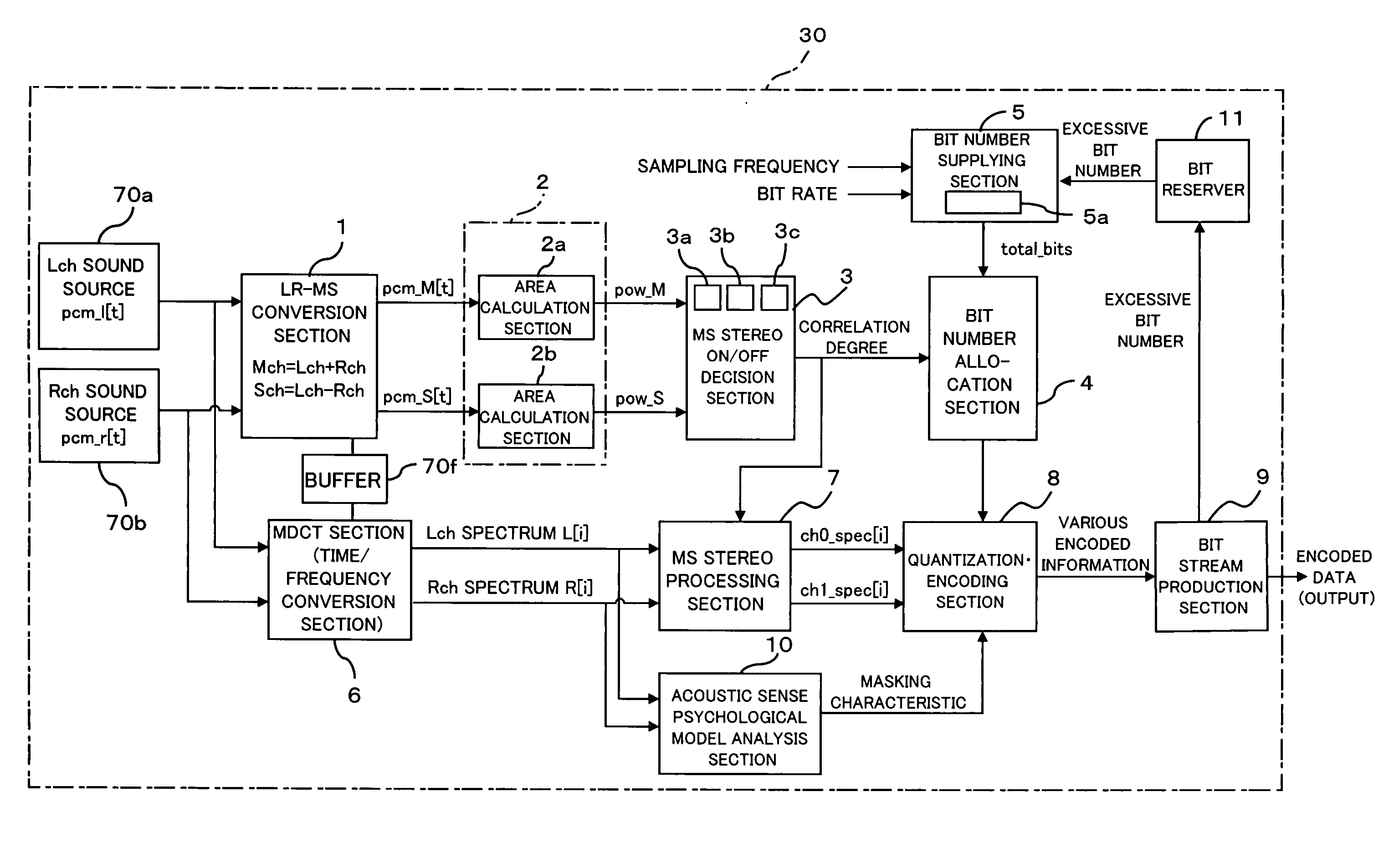
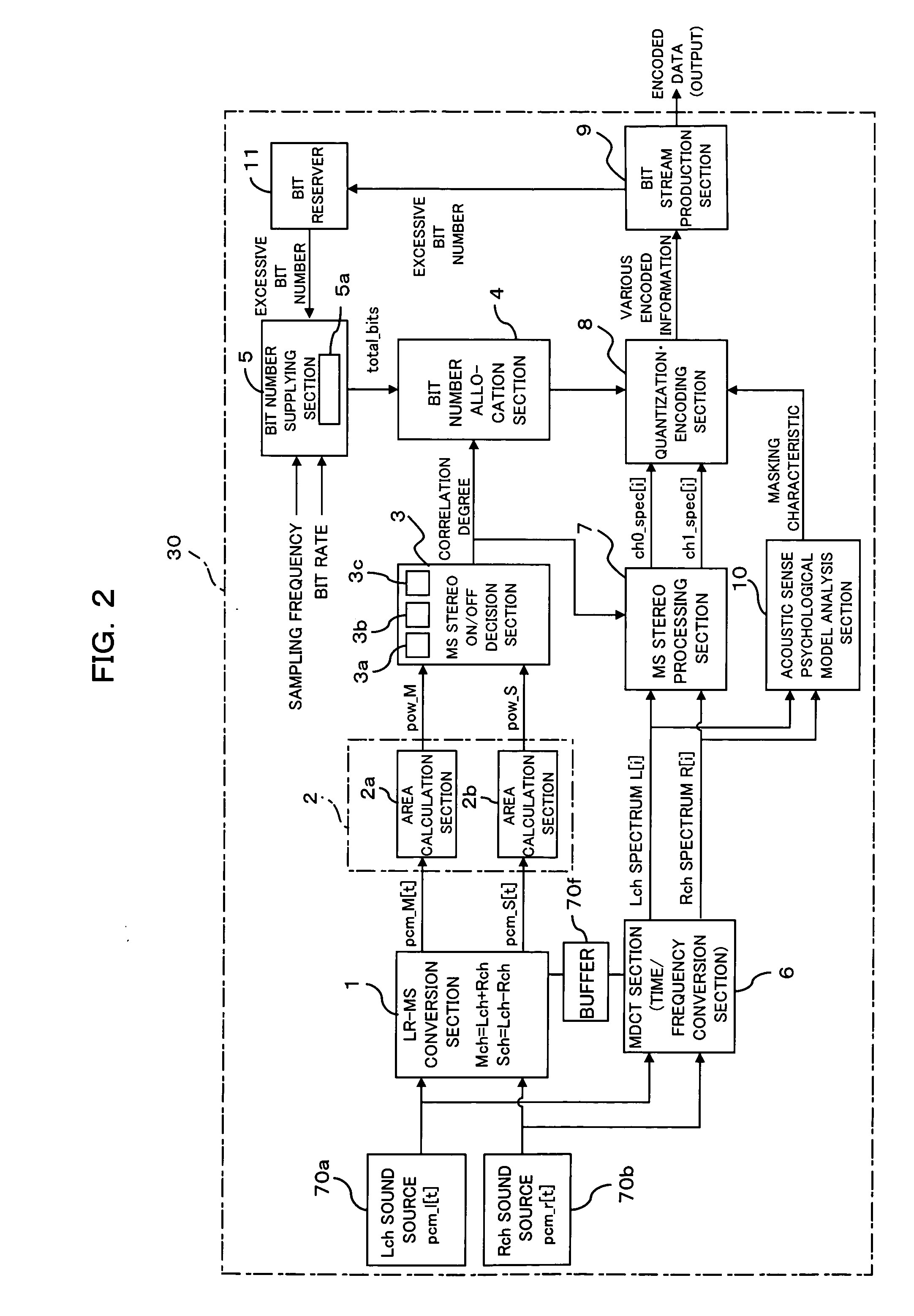
[0045] It is an object of the present invention to provide an audio encoding apparatus for stereo audio encoding an L-channel PCM signal and an R-channel PCM signal and a frame region allocation circuit for an audio encoding apparatus which can efficiently allocate encoded data of the L-channel and the R-channel without involving variation or modification to an existing frame format and can optimally perform MS stereo ON / OFF control and control of a bit allocation amount or a frame region for the inputted PCM signals and particularly can adjust the size of a frame region upon encoding without being limited by a sampling rate, a transmission rate and so forth.

Problems solved by technology

The appearance of quantization errors signifies that, when the decoding apparatus side decodes the difference spectrum, also errors on the reference channel side appear.
In other words, the one channel signal leaks to the otheR-channel signal, and this gives rise to appearance of noise.
Here, if the correlation between the 2 channels is high, then since the power of the difference spectrum is low, the acoustic signal processing circuit cannot detect the noise described above.
However, when the power of the difference spectrum is high, the noise described above can be detected and gives rise to degradation of the sound quality.
Accordingly, the acoustic signal processing circuit disclosed in the Patent Document 1 turns off the MS stereo process when the correlation degree between the two channels is low and therefore cannot detect the noise or suppress appearance of noise caused by leakage of a channel signal.

Method used


Image

  • Audio encoding apparatus and frame region allocation circuit for audio encoding apparatus
  • Audio encoding apparatus and frame region allocation circuit for audio encoding apparatus
  • Audio encoding apparatus and frame region allocation circuit for audio encoding apparatus

Examples


first embodiment

A. Description of the Present Invention

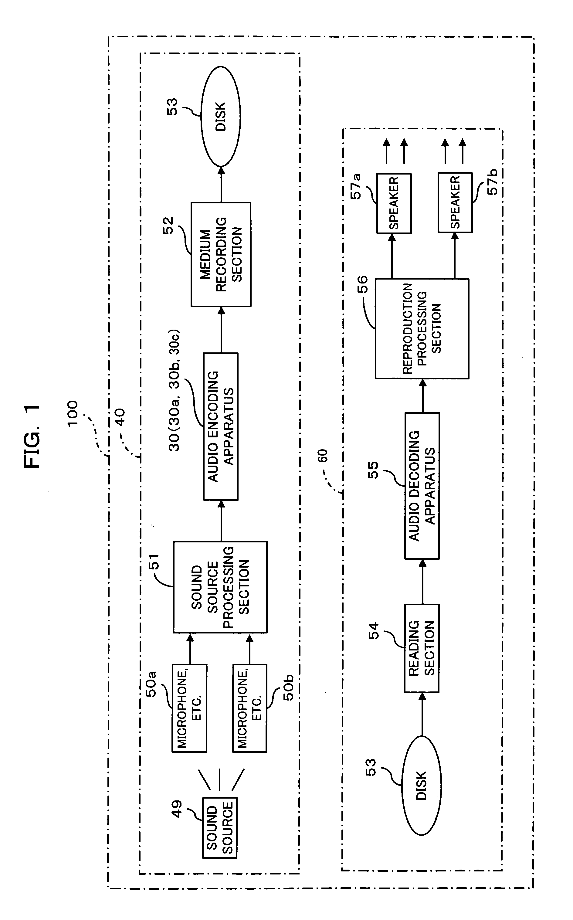
[0090]FIG. 1 is a block diagram showing an example of an audio recording and reproduction system according to a first embodiment of the present invention. The audio recording and reproduction system 100 shown in FIG. 1 acquires a sound source such as sound, voice, music or the like using stereo channels of an L-channel and an R-channel and performs an audio encoding process for the acquired sound source signals (sound source data) to record the signals on a digital disk, and further performs an audio decoding process for the digital disk to perform stereo reproduction of the recorded signals. The audio recording and reproduction system 100 includes an audio recording apparatus 40, a digital disk 53, and an audio reproduction apparatus 60.

1. Configuration of the Audio Recording and Reproduction System 100

[0091] The audio recording apparatus 40 audio encodes a sound source signal for outputting a sound source and records an audio encoded frame ...

second embodiment

B. Description of the Present Invention

[0200] In the first embodiment, the PCM signals from the L-channel PCM signal production section 70a and the R-channel PCM signal production section 70b are both time base signals and are converted into signals of the M-channel and the S-channel and audio encoded in the time domain.

[0201] In the second embodiment, however, calculation of a waveform area is performed in the frequency domain. Further, an audio recording and reproduction system in the second embodiment is same as the audio recording and reproduction system 100.

[0202]FIG. 16 is a block diagram of an audio encoding apparatus according to the second embodiment of the present invention. Referring to FIG. 16, the audio encoding apparatus 30b shown performs stereo audio encoding of an L-channel PCM signal and an R-channel PCM signal. The audio encoding apparatus 30b is different from the audio encoding apparatus 30 and 30a in that the PCM signals from the L-channel PCM signal producti...


PUM


Abstract

An audio encoding apparatus for stereo audio encoding an L-channel PCM signal and an R-channel PCM signal efficiently allocates encoded data of the L-channel and the R-channel without varying an existing format and performs MS stereo on / off control and controls of a bit allocation amount or a frame region for the inputted PCM signals while miniaturization of the apparatus can be anticipated. A correlation degree calculation section calculates, based on the PCM signals of the L-channel and the R-channel, a correlation degree between the PCM signals, and decision section decides whether or not a stereo encoding process should be performed based on the calculated correlation degree. An allocation section allocates regions for individually storing a difference signal and a sum signal between the PCM signals based on a result of the decision, and an audio encoding section encodes the difference signal and the sum signal based on the allocated regions.

Description

BACKGROUND OF THE INVENTION [0001] 1) Field of the Invention [0002] The present invention relates to an audio encoding apparatus which employs a digital compression encoding method such as, for example, the MP3 (MPEG3 Layer 3), the MPEG2-AAC (Moving Picture Experts Group 2—Advanced Audio Coding) or the like, and more particularly to an audio encoding apparatus having an MS stereo (Middle / Sides stereophonic) function and a frame region allocation circuit for an audio encoding apparatus. [0003] 2) Description of the Related Art [0004] With the progress of a digital compression technique in recent years, a portable terminal, a personal computer and so forth are formed so as to be ready for several data formats such as text, audio (audio frequency), sound, and video data formats. [0005] A compression encoding method for an audio signal (audio data or audio signal data) is standardized as the MPEG1 Audio by the MPEG, and three different modes of the Layer 1 to the Layer 3 are prescribed....

Claims


Application Information

Patent Timeline
IPC IPC(8): G10L19/008G10L19/02H03M7/30H04S1/00
CPCG10L19/008
Inventor EGUCHI, NOBUHIDE
Owner FUJITSU MICROELECTRONICS LTD
Learn More