Method for driving a bidirectional motor to rotate a fluid circulation pump

a technology of fluid circulation and bidirectional motor, which is applied in the direction of motor/generator/converter stopper, positive displacement liquid engine, dynamo-electric converter control, etc., can solve the problems of high cost of devices, high cost, and indifferent rotation of rotors clockwise or anticlockwis

Active Publication Date: 2005-07-21
ASKOLL HLDG SRL
View PDF3 Cites 7 Cited by
  • Summary
  • Abstract
  • Description
  • Claims
  • Application Information

AI Technical Summary

Benefits of technology

[0015] Therefore, due to the invention, by means of continual interruptions and following starting steps of the bidirectional motor it is probabilistically certain that, at least for a fraction

Problems solved by technology

The main drawback is due to the fact that the synchronous motors, through which pumps are rotated, are bidirectional motors, i.e., on starting, the rotor can indifferently be rotated clockwise or anticlockwise.
These devices have a very high cost, both of production and of application to the motor, and this high cost is a not-yet-overcome obstacle, prevailing on the need to optimise energy efficiency, so that the use

Method used


Image

  • Method for driving a bidirectional motor to rotate a fluid circulation pump
  • Method for driving a bidirectional motor to rotate a fluid circulation pump
  • Method for driving a bidirectional motor to rotate a fluid circulation pump

Examples


first embodiment

[0032] the method according to the invention is now shown with reference to FIG. 3 by means of a first flow chart.

[0033] In this application the method provides that an operation time interval Ttot of the centrifugal pump 10 is initially imposed for the fluid circulation in the corresponding circuit 15.

[0034] In a first step A, at the time to, the synchronous motor 14 start-up is operated by the control unit 16.

[0035] The synchronous motor 14 is thus started in either rotation direction, and in this condition it is kept rotating for a first time fraction Δt1 (step B), conveniently calculated to allow the centrifugal pump 10 to steadily rotate.

[0036] Afterwards, at a predetermined instant t2 (step C) the synchronous motor 14 power feeding is interrupted by means of the commutation switch 19, and a second time fraction Δt2 is let passing, which is conveniently calculated by the calculation unit 18 to wait the real shutdown of the centrifugal pump 10 (step D).

[0037] Once the centri...

second embodiment

[0045] In the method according to the invention the fluid circulation device 11 comprises a centrifugal pump 10 provided with such convenient known constructive asymmetries as to influence the probability for the synchronous motor 14 to rotate more in one direction than in the other.

[0046] These constructive asymmetries can be both mechanical and hydraulic and electric.

[0047] For example, it is known to provide a mechanical asymmetry by conveniently bending the blades of the impeller 13 in order to increase the power absorbed by the centrifugal pump 10, when it is rotated in the direction corresponding to the lowest hydraulic efficiency.

[0048] The method is implemented with the same embodiments described with reference to the diagram of FIG. 3.

[0049] Therefore, by cyclically repeating the interruption and start of the synchronous motor 14 in the predetermined time interval Ttot, it is possible to obtain a probability rate comprised between 50% and 99% that the centrifugal pump 10...

third embodiment

[0050]FIG. 4 shows the method according to the present invention, with reference to a second flow chart.

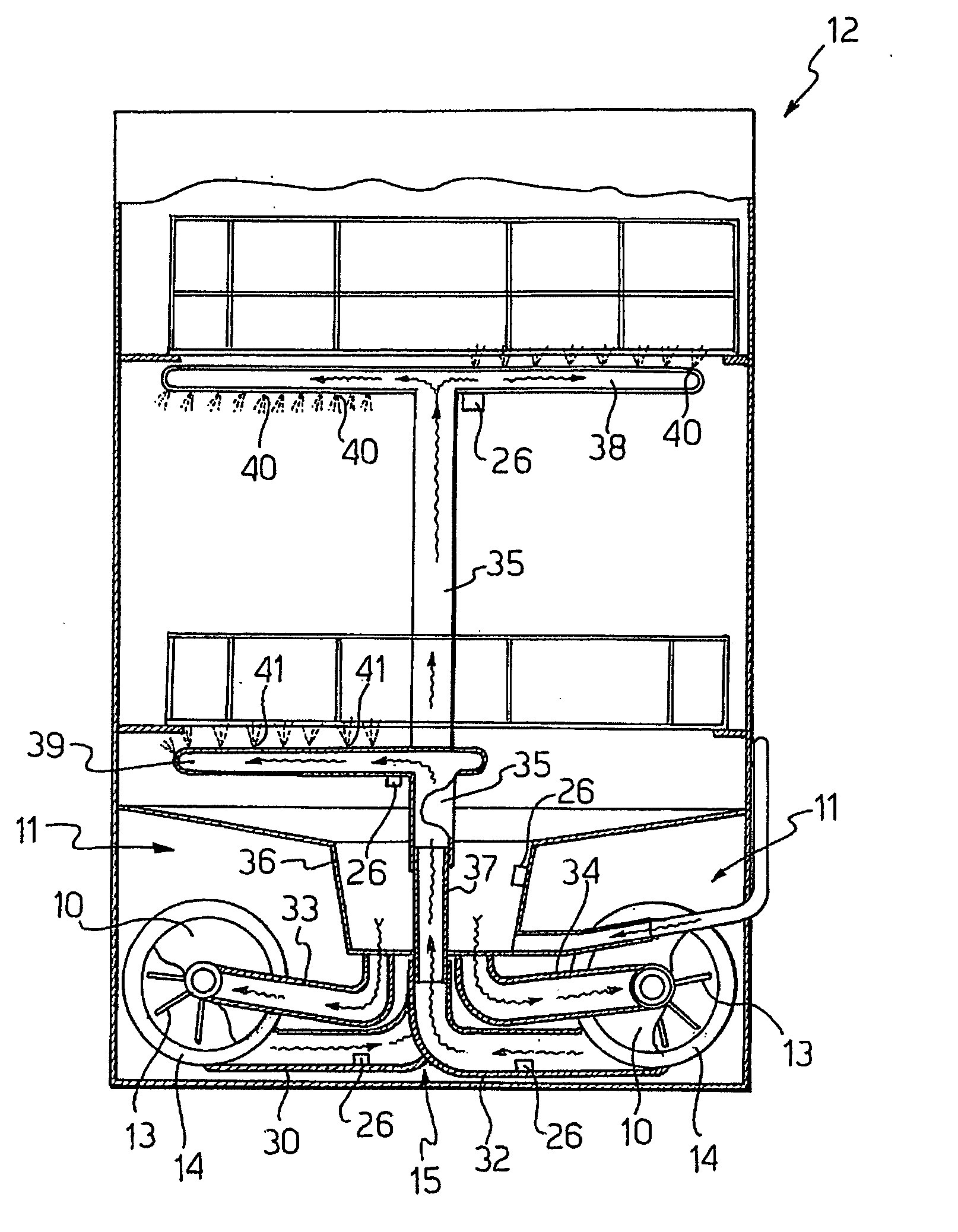
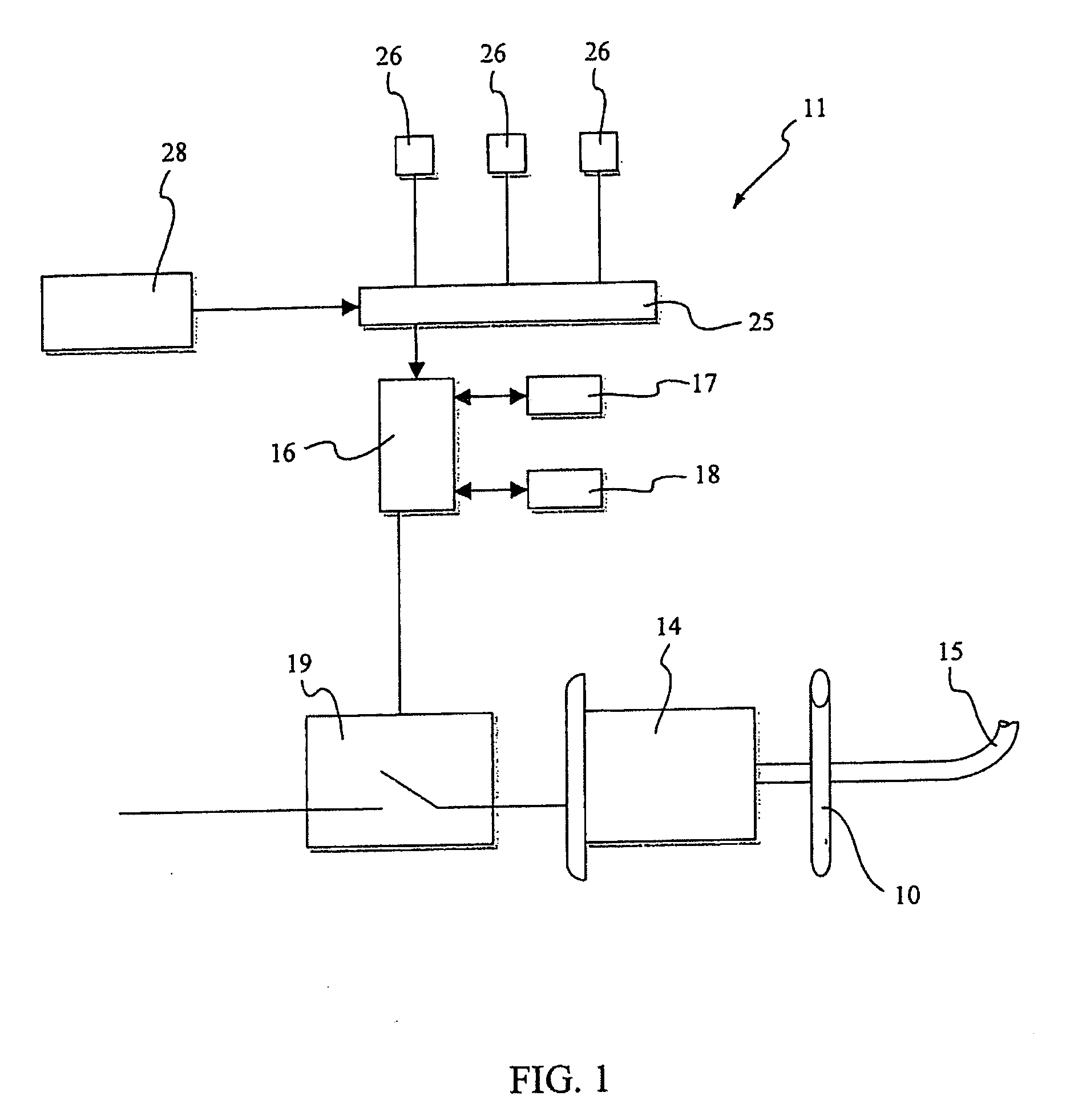
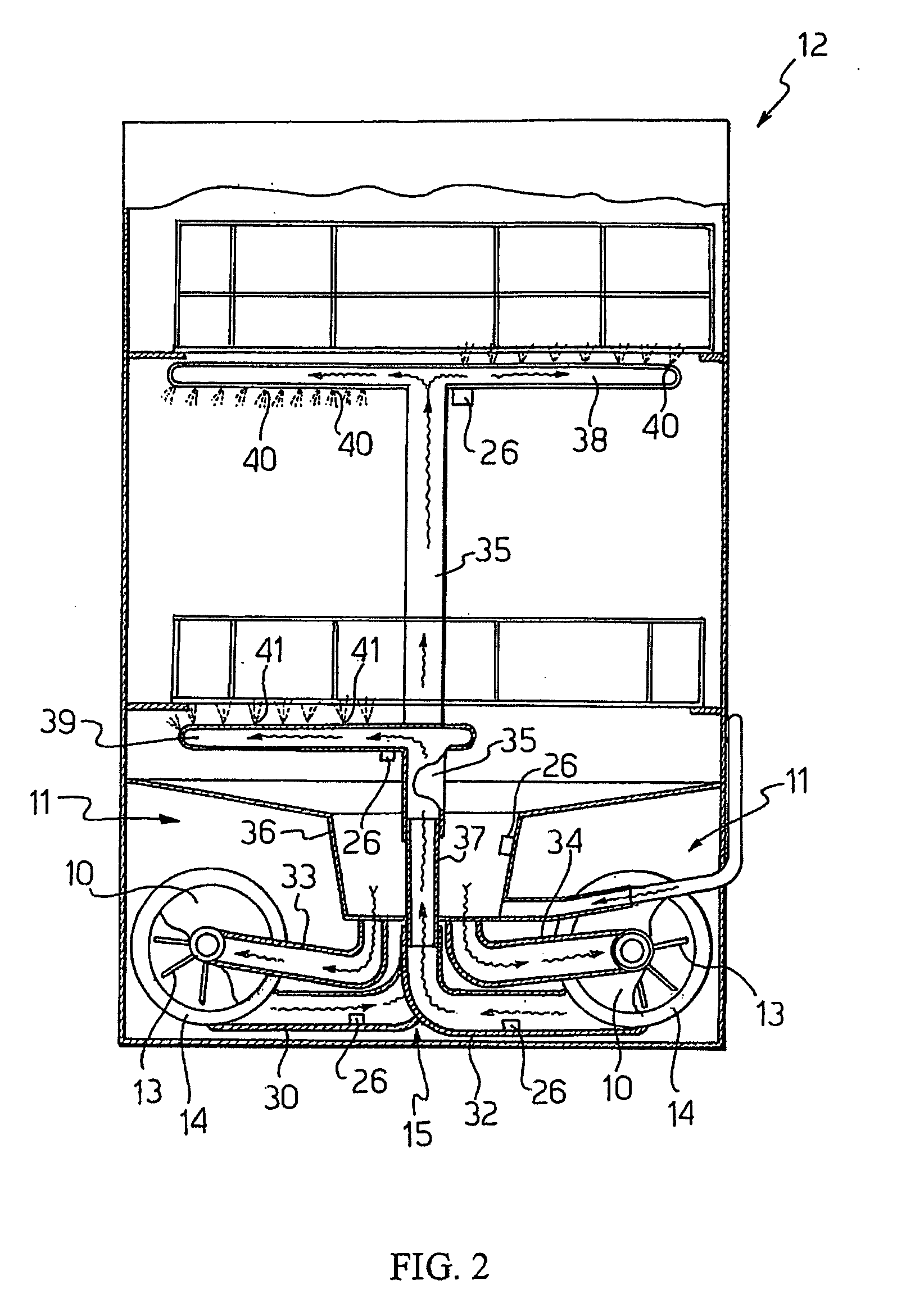
[0051] In this application the fluid circulation device 11 comprises a control circuit 25 of the centrifugal pump 10 associated to sensors 26, which is functionally connected to the control unit 16.

[0052] The control circuit 25 is of the known type and it is configured to detect, by means of the sensors 26, the hydraulic speed of the centrifugal pump 10, by measuring for example the flow rate or the pressure of the fluid outputted from the centrifugal pump 10, or the noise produced during the operation thereof, or the current absorbed by the motor or other similar quantities.

[0053] The control circuit 25 is thus capable to indirectly detect the rotation direction of the synchronous motor 14.

[0054] In particular, in this application, the method provides that a time interval Ts of iterative interruptions and starts of the synchronous 14 is imposed. I.e. the interruption and start...


PUM


Abstract

A method for starting a motor (14) with a bidirectional rotation direction, to rotate a fluid circulation centrifugal pump (10) having a predetermined optimum hydraulic efficiency depending on the starting rotation direction thereof. The method provides an initial motor (14) starting in either rotation direction, with subsequent pump (10) rotation in the same direction and, subsequently, a periodical interruption and restoration of the motor (14) power feeding as many times (N, N′) as to ensure the motor (14) starting, at least one or more times within a predetermined time interval (Ttot, Ts), in the rotation direction which corresponds to the predetermined pump (10) optimum hydraulic speed.

Description

FIELD OF APPLICATION [0001] The present invention relates to a method for starting a bidirectional motor, i.e. having an undifferentiated rotation direction on starting, to rotate a fluid circulation centrifugal pump, but having a predetermined optimum hydraulic efficiency depending on the starting rotation direction thereof. [0002] The present invention also relates to a fluid circulation device and to a washing machine for implementing said method. PRIOR ART [0003] The need to manufacture fluid circulation centrifugal pumps for household or industrial appliances such as washing machines, like dish-washing machines, washers, or for heating or conditioning systems, having the best possible hydraulic efficiency, is well known. [0004] Besides the above-mentioned need, there is also the need, mainly for dish-washing machines or washers, to decrease as much as possible the pump hydraulic power and consequently also the electric power supplied to the motor, in order to reduce therefore b...

Claims


Application Information

Patent Timeline
IPC IPC(8): A47L15/42D06F33/47D06F39/08F04D15/00F04D29/22
CPCA47L15/0047A47L15/4225A47L2401/34A47L2501/04Y02B40/42D06F39/08F04D15/0077F04D29/2283A47L2501/05Y02B40/00D06F33/47
Inventor MARIONI, ELIO
Owner ASKOLL HLDG SRL
Why Eureka
Try Eureka