
Bone fracture treatment devices and methods of their use

Inactive Publication Date: 2005-07-21
EXPANDING ORTHOPEDICS
View PDF99 Cites 224 Cited by
  • Summary
  • Abstract
  • Description
  • Claims
  • Application Information

AI Technical Summary

Benefits of technology

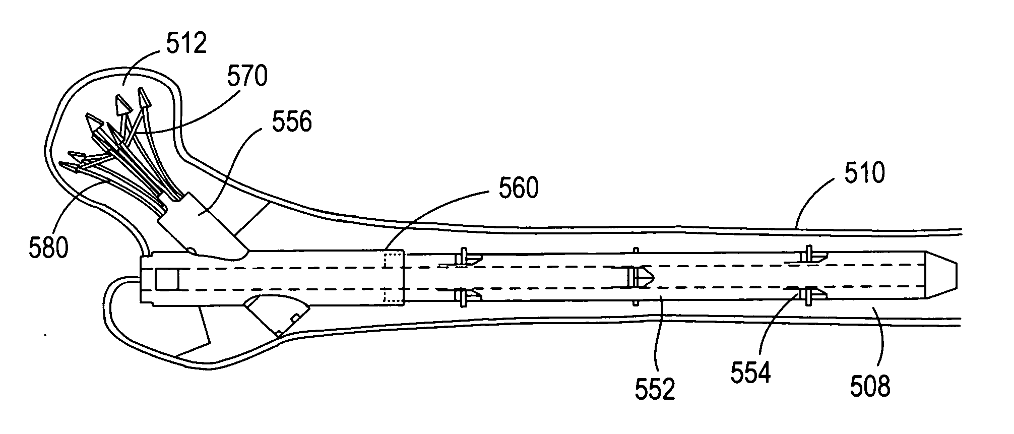
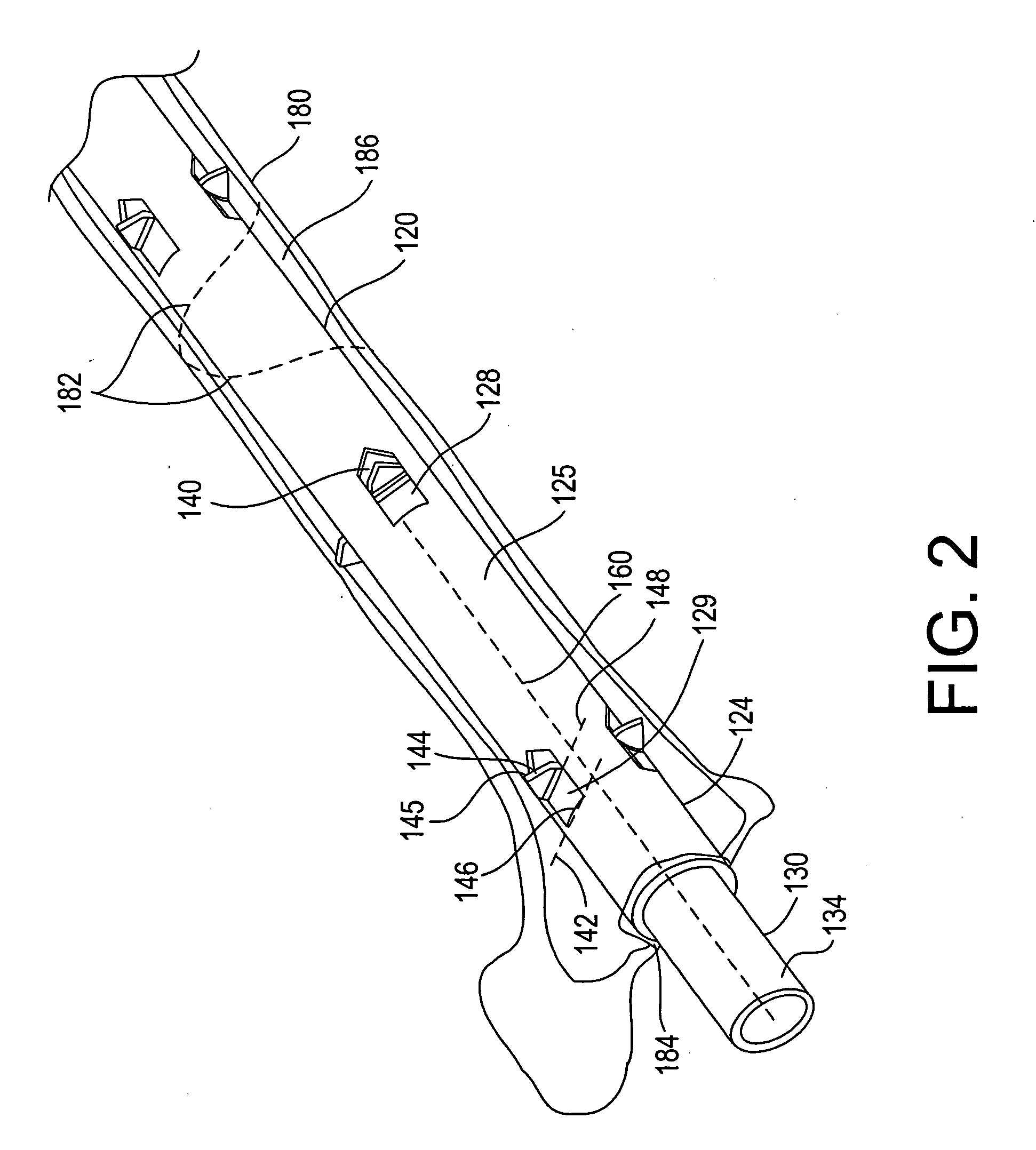
[0012] In accordance with a third aspect of the present inventions, a method for treating the bone is provided. The method comprises inserting the bone treatment device into the bone, e.g., along the medullary canal of the bone or laterally into the bone. The method further comprises deploying the anchoring element(s) out of the opening(s) (e.g., by using one of the previously described actuators) to anchor the device within the bone, e.g., by hinging the anchoring element(s) outward from the tubular wall. If the bone is fractured, anchoring of the device will help stabilize the fractured bone.

Problems solved by technology

Some of the problems associated with conventional intramedullary fixation methods include lack of rotation stability (i.e., fractured bone segments connected by a nail can rotate relative to each other), lack of longitudinal stability (i.e., fractured bone segments connected by a nail can move relative to each other along an axis of the nail), collapse of the fracture site in some fracture types, and / or undesired backup of nails.
In addition, intramedullary fixation methods may introduce interlocking screws across the nail, creating some disadvantages.
This additional step generally makes the operation longer and more complicated, and may require additional skin incisions and / or longer use of an image intensifier (X-ray).
Furthermore, undesired gaps between the bone ends may originate from the screws, which are permanent unless removed in a new operation.
In contaminated fractures, metallic intramedullary nails may propagate contamination through the entire canal, despite attempts at cleaning the fracture site, which may lead to bone infection.

Method used


Image

  • Bone fracture treatment devices and methods of their use
  • Bone fracture treatment devices and methods of their use
  • Bone fracture treatment devices and methods of their use

Examples


Embodiment Construction

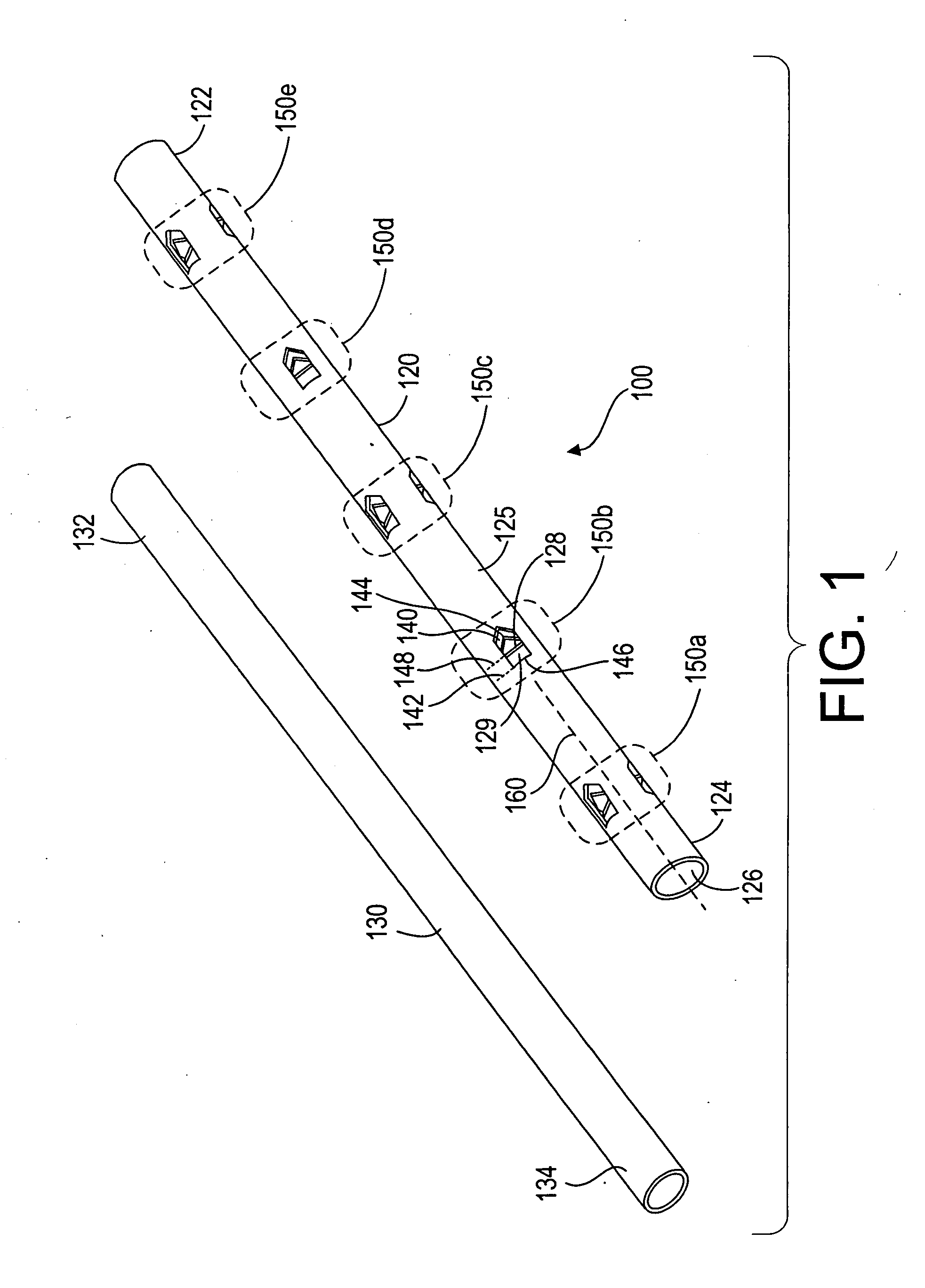
[0028] Referring now to FIGS. 1 and 2, a bone treatment kit 100 in accordance with one embodiment of the invention will now be described. The kit 100 generally comprises a bone treatment shaft 120 and an actuator 130 that facilitates anchoring of the bone treatment shaft 120 along a medullary canal of a bone. The bone shaft 120 has a first end 122, a second end 124, and a tubular wall 125 defining a lumen 126 that extends between the first and the second ends 122, 124. The actuator 130 has a first end 132 and a second end 134. The actuator 130 is sized such that it can be inserted into the lumen 126 of the bone shaft 120 during use. The bone shaft 120 and the actuator 130 can be made from a variety of biocompatible materials, such as plastics, polymer, metals, alloys, or ceramics. The bone shaft 120 and the actuator 130 can also be made from a bioabsorbable material, a tissue engineered material, a shape memory alloy or polymer, such as, nitinol, or other resilient materials, such a...


PUM


Abstract

A bone treatment device comprises a shaft having a tubular wall, a lumen extending within the tubular wall, openings through the tubular wall, and anchoring elements adjacent the openings that can be deployed out of the openings in the presence of an actuating force within the shaft lumen. The bone treatment device may further comprise an actuator configured to be received within the shaft lumen to deploy the anchoring elements out of the openings.

Description

CROSS-REFERENCE TO RELATED APPLICATIONS [0001] The present application claims priority under 35 U.S.C. §119 to U.S. Provisional Patent Application Ser. No. 60 / 536,918, entitled “Intramedullary Devices and Methods of Using Same” filed Jan. 16, 2004, the complete contents of which are incorporated herein by reference.FIELD OF THE INVENTION [0002] This invention relates generally to medical devices and methods and, more specifically, to devices and methods for stabilizing fractured bones and / or for fixing objects to bones. BACKGROUND OF THE INVENTION [0003] Fractures of limb bones have been treated with internal fixation devices, such as plates lying on the surface of a bone, nails running inside the medullary canal of a fractured bone, and / or screws affixing both ends of a fractured bone together. These internal fixation devices may provide reasonable structural rigidity and / or stability to the fractured bone without compromising some of the strain desired to stimulate bone cells. [00...

Claims


Application Information

Patent Timeline
IPC IPC(8): A61B17/00A61B17/58A61B17/68A61B17/72A61B17/78A61B17/86A61F2/00A61F2/30A61F2/44
CPCA61B17/68A61F2002/30579A61B17/725A61B17/7266A61B17/7283A61B17/744A61B17/8625A61B2017/00004A61B2017/00867A61F2/0077A61F2/30749A61F2/34A61F2/3662A61F2/446A61B17/686
Inventor LEVY, MARK M.GREENBERG, ILAN
Owner EXPANDING ORTHOPEDICS
Learn More