
Method and apparatus of controlling electric power for translation lookaside buffer

a technology of lookaside buffer and electric power, applied in the field of tlb, can solve the problems of increasing the current of off-state, increasing the electric power consumption of the processor during inactivation, and little attention to the reduction of power consumption, so as to reduce unnecessary power consumption

Inactive Publication Date: 2005-07-21
FUJITSU LTD
View PDF3 Cites 51 Cited by
  • Summary
  • Abstract
  • Description
  • Claims
  • Application Information

AI Technical Summary

Benefits of technology

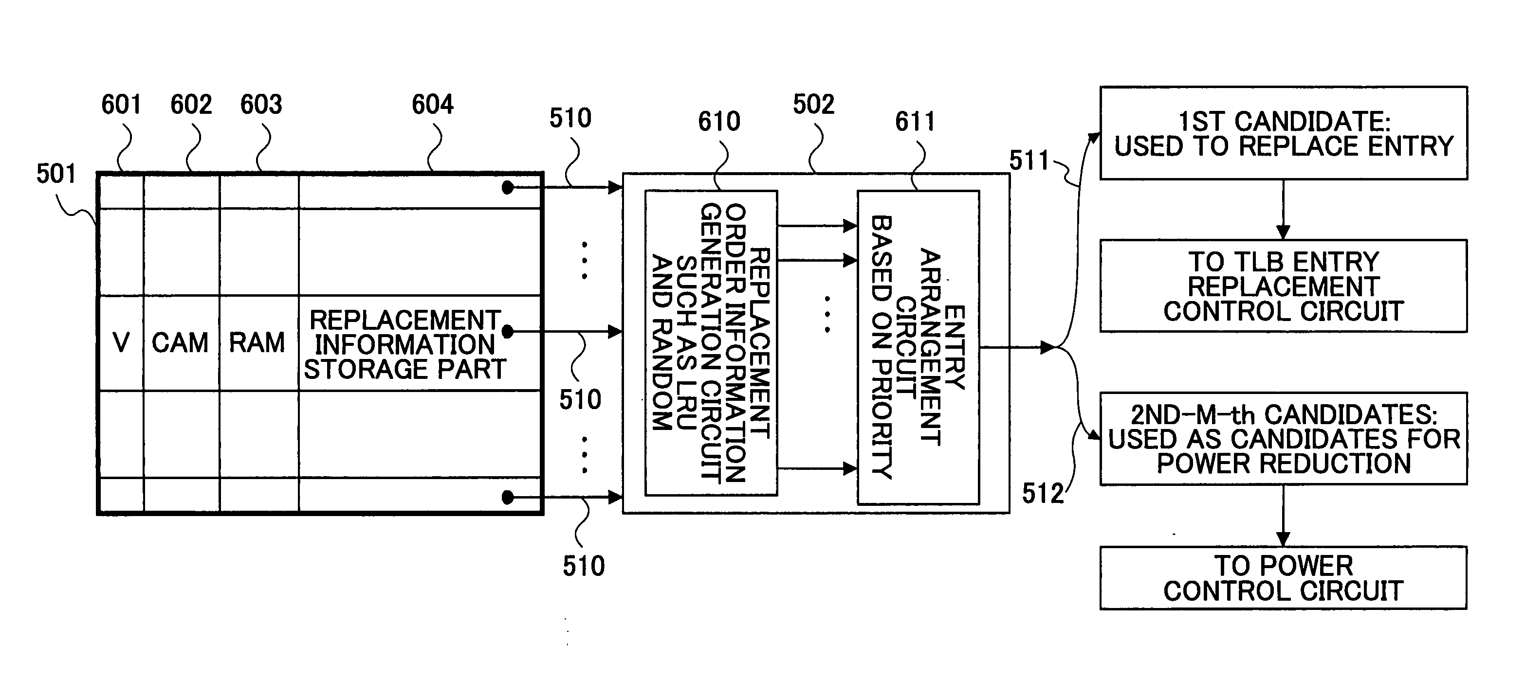
The present invention aims to reduce unnecessary power consumption in a central processing device with a translation lookaside buffer (TLB) and an entry replacement mechanism. The method involves selecting certain entries in the TLB based on predefined criteria and controlling power supply to those entries. This helps to disconnect unused entries from power supply, reducing power consumption due to unnecessary leakage current. Overall, the invention helps to optimize power consumption and improve efficiency of the central processing device.

Problems solved by technology

However, if a transistor element has a lower threshold voltage (Vth) as noted above, the off-state leakage current may increase when the transistor element is off-state.
That results in increases in electric power consumption during inactivation of the processor.
However, although TLB within a processor consumes electric power like cache RAMs, little attention on reduction in power consumption has been focused on TLB because of dominant seeking of speedup of TLB.
As a result, TLB consumes a large amount of electric power during normal operation as well as inactivation.
Thus, it is impossible to easily reduce electric power consumption during normal operation and inactivation.
That increases an unnecessary amount of leakage current, resulting in further increases in power consumption.

Method used


Image

  • Method and apparatus of controlling electric power for translation lookaside buffer
  • Method and apparatus of controlling electric power for translation lookaside buffer
  • Method and apparatus of controlling electric power for translation lookaside buffer

Examples


Embodiment Construction

[0028] In the following, embodiments of the present invention will be described in conjunction of the drawings.

[0029] At the beginning, an exemplary fundamental operation of TLB will be described with reference to FIG. 1 through FIG. 4.

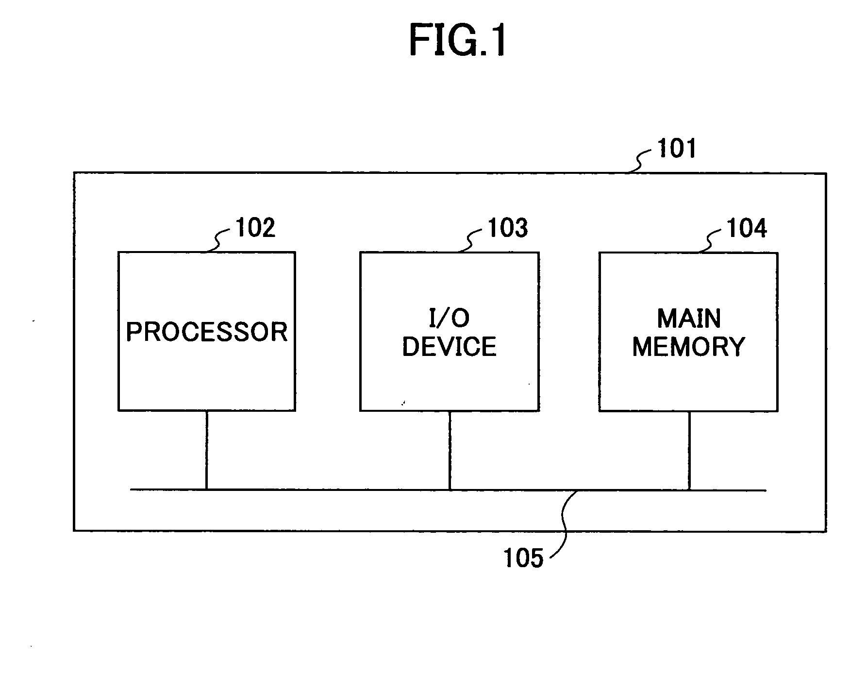
[0030]FIG. 1 is a block diagram roughly illustrating a typical computer system. Referring to FIG. 1, a typical computer system 101 includes a processor 102 as a central processing unit, an input / output (I / O) device 103 such as a keyboard and a monitor, a main memory 104 for storing data and programs and a bus 105 for connecting among the processors 102, the I / O device 103 and the main memory 104.

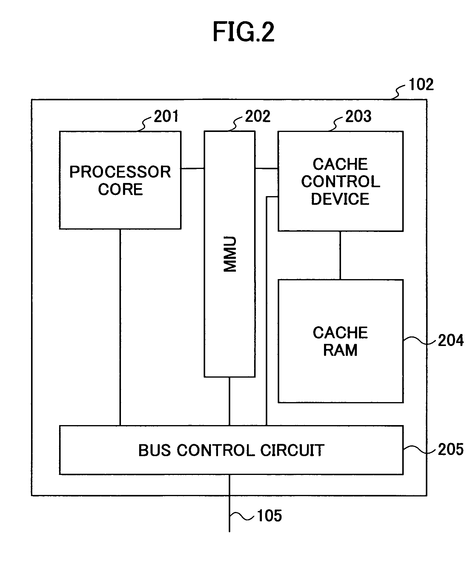
[0031]FIG. 2 is a block diagram roughly illustrating an exemplary internal structure of the processor 102 of FIG. 1. Referring to FIG. 2, the processor 102 includes a processor core 201, a memory management unit (MMU) 202, a cache control device 203, a cache RAM 204 and a bus control circuit 205.

[0032]FIG. 3 illustrates a conventional memory management uni...


PUM


Abstract

The present invention is intended to reduce unnecessary power consumption by controlling disconnection of entries unused in a translation lookaside buffer (TLB) for a long time. In an aspect of the present invention, there is provided a method of controlling electric power consumed for a translation lookaside buffer (TLB) within a central processing device having the TLB and an entry replacement mechanism wherein the TLB includes a plurality of entries and performs translation from a logical address to a physical address and the entry replacement mechanism replaces the entries of the TLB, the method including the steps of: selecting one or more entries among the plurality of entries of the TLB in accordance with one or more predefined criteria based on an output from the entry replacement mechanism, and controlling electric power supplied to the selected entries.

Description

CROSS-REFERENCE TO RELATED APPLICATIONS [0001] The present application is a U.S. continuation application filed under 35 USC 111(a) claiming benefit under 35 USC 120 and 365(c) of PCT application JP03 / 06359 filed May 21, 2003, the contents of which are hereby incorporated herein by reference.BACKGROUND OF THE INVENTION [0002] 1. Field of the Invention [0003] The present invention generally relates to TLB (Translation Lookaside Buffer for translation from logical addresses to physical addresses) incorporated in a processor such as a central processing device, and more particularly, to reduction in electric power consumption for TLB. [0004] 2. Description of the Related Art [0005] Recent development of high-speed processors (central processing devices) has promoted higher operation speed of transistor elements in the processors. The faster operation of a transistor element is achieved by lowering a threshold voltage (Vth) of the transistor element and thereby raising the current level...

Claims


Application Information

Patent Timeline
Patent Type & Authority Applications(United States)
IPC IPC(8): G06F1/32G06F12/08G06F12/10G06F12/12G11C8/06
CPCG06F1/3225G06F1/3275G06F12/1027Y02B60/1228G06F2212/1028G11C8/06Y02B60/1225G06F12/126Y02D10/00
Inventor YOSHIMI, KOICHI
Owner FUJITSU LTD
Learn More