Interlocking conformable retainer wall system

a retainer wall and conformable technology, applied in the field of retainer walls, can solve the problems of reducing the aesthetic appearance of retainer walls in certain applications, limiting the ability to utilize such wall systems, and affecting the aesthetics of retainer walls, so as to improve the aesthetic appearance of wall segments, avoid susceptibility to rot or corrosion, and ensure the effect of bending

Inactive Publication Date: 2005-07-28
PLAYCARE
View PDF16 Cites 18 Cited by
  • Summary
  • Abstract
  • Description
  • Claims
  • Application Information

AI Technical Summary

Benefits of technology

[0021] In a preferred embodiment of each of the above embodiments of the invention the vertical members comprise elongate cylindrical members, having a wood grain impressed on the exterior of such cylindrical members to provide the appearance of wooden logs and thus provide a decorative effect and/or improve the aesthetic appearance of the wall segments. One or more logs in each wall segment possess a longitudinal bore, to permit insertion of a pin member which is of such a length so as to also be inserted into the ground so as to thereby retain the respective wall element in an desired conformed position.
[0022] In a preferred embodiment, to avoid susceptibility to rot or corrosion and to assist in forming the cylindrical members with an exterior wood grain exterior ap...

Problems solved by technology

Disadvantageously, however, the wall elements of the above prior art retainer wall system are not suitable for creating a retainer wall having a continuous curvilinear profile.
While shorter [around 4 feet(1.3 m) in length] wall elements may be used, the contour can only comprise a number of discrete linear elements due to the rigidity of the wall elements, and a continuous curvilinear contour for the retainer wall cannot be obtained, thus detracting in certain applications from the aesthetic appearance of such retainer wall.
This is a serious limitation of such prior art design, since it limits the ability to utilize such wall system in high visibility urban areas such as parks and children's play areas, where aesthetics are importan...

Method used


Image

  • Interlocking conformable retainer wall system
  • Interlocking conformable retainer wall system
  • Interlocking conformable retainer wall system

Examples


Embodiment Construction

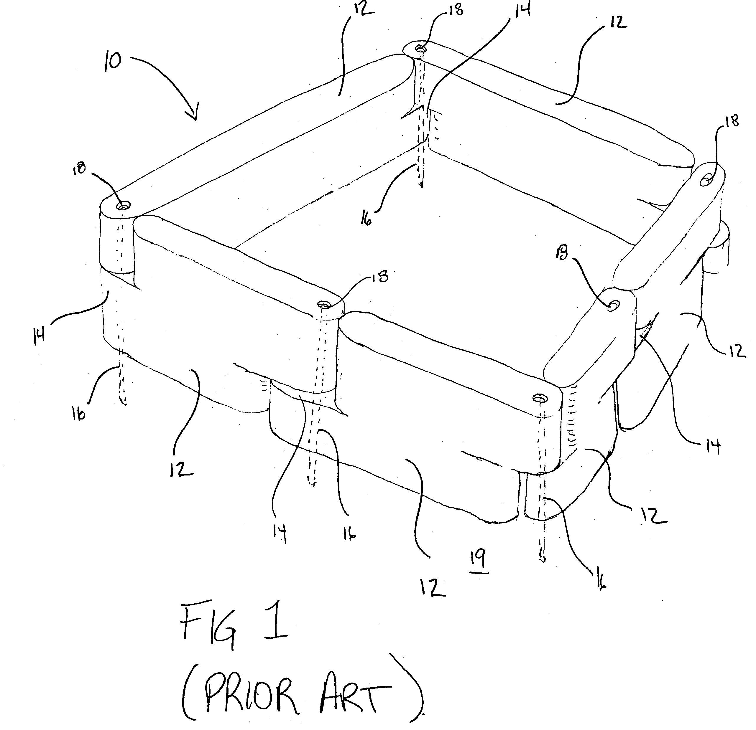
[0032]FIG. 1 shows a retainer wall system 10 of the prior art, having a plurality of interlocking wall elements comprising a relatively flat, elongate members 12 of a relatively inflexible plastic material. Each elongate member 12 possesses a protruding portion 14 which allows interlocked coupling to an adjacent elongate member 14 via a pin member 16. Pin member 16 passes through an aperture 18 in each elongate member 12 and thereafter into the ground 19, to retain the plurality of elongate members 12 in a fixed position to thereby serve as a retainer wall system 10.

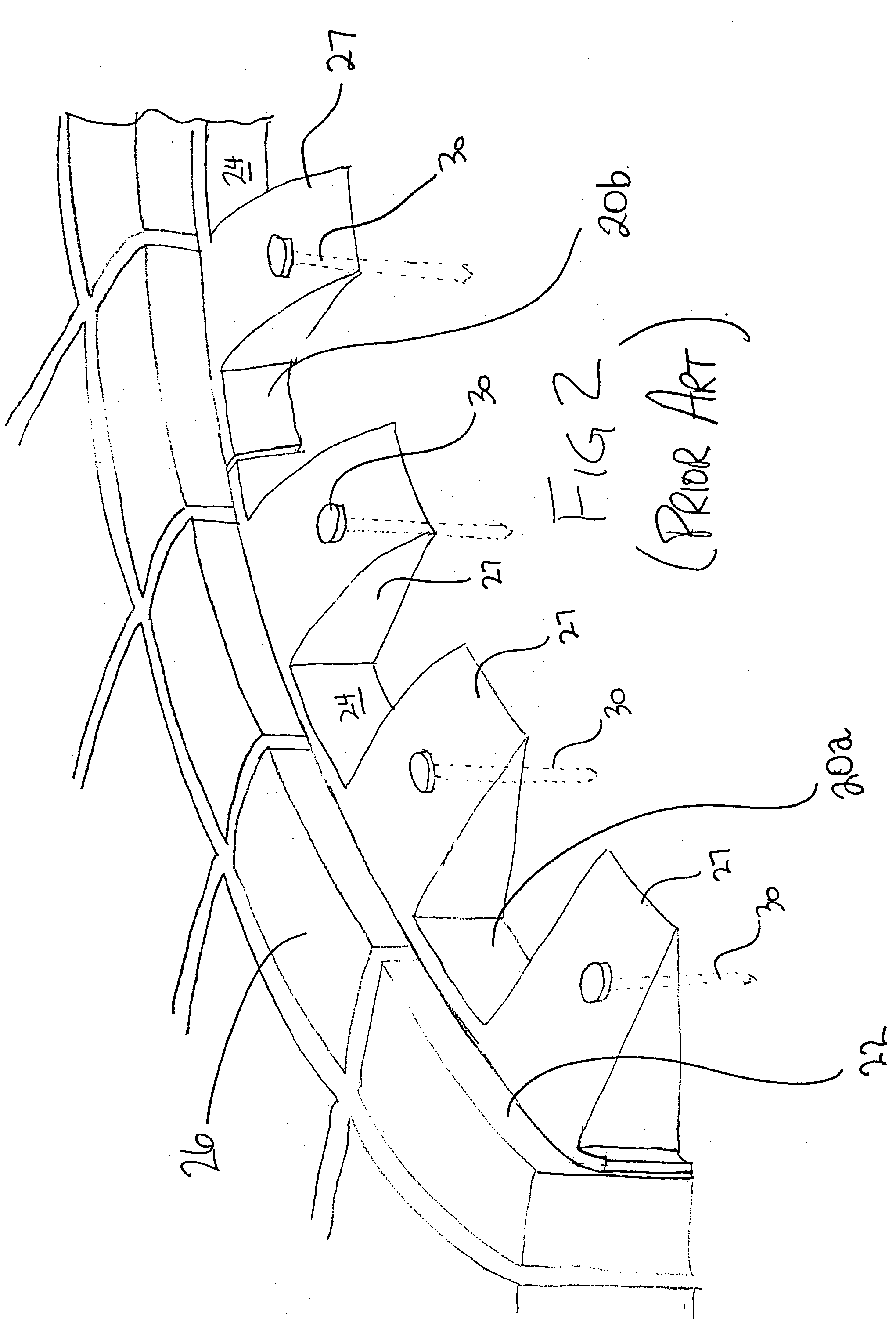
[0033] Disadvantageously, elongate wall elements 12 of the prior art retainer wall system 10 are each of approximately 4 feet (1.3 m) in length, up to 10 feet (3.3 m) in length, and are not suitable for creating a retainer wall having a continuous curvilinear profile. Instead, should a curvilinear profile be attempted to be used, the closest approximation comprises a number of discrete linear segments comprised of a plu...


PUM


Abstract

A retainer wall system comprised of interlocking wall segments for use as a retainer wall. Each wall segment is resiliently flexible to allow the retainer wall to follow a curvilinear/curved profile. In a preferred embodiment the wall segments comprise a plurality of substantially vertical elongate cylindrical members configured to resemble wooden logs, arranged in parallel in substantially mutually adjacent position. Each of the logs are coupled to an adjacent log by a resiliently flexible web member so as to permit flexible bending of each of each of the wall segments about a vertical axis therethrough. One or more of the logs making up each wall segment possess a longitudinal bore extending substantially along a vertical longitudinal axis of such log, so as to permit a pin member to be inserted therethough and into the ground so as to retain the wall segments in a desired conformed position.

Description

FIELD OF THE INVENTION [0001] This invention relates to retainer walls, and in particular, to an interlocking retainer wall system which is flexibly conformable over its entire length to a desired contour. BACKGROUND OF THE INVENTION AND DESCRIPTION OF THE PRIOR ART [0002] Retainer walls are frequently used in various landscape applications. For example, in recreational play areas and parks containing children's play equipment, such areas may be surrounded by a retainer wall to retain sand within such play area beneath the children's play equipment, and to define the play area. Similarly, retainer walls may also surround shrub and flower beds, to keep out small children and animals. [0003] At least one type of retainer wall system is presently commercially available on the market for use as a retainer wall in children's play areas. [0004] Specifically, in such commercially available retainer wall system, a number of interlocking wall elements are utilized, each of approximately 1.0 ...

Claims


Application Information

Patent Timeline
IPC IPC(8): A01G9/28
CPCA01G1/08A01G9/28
Inventor WILLIAMS, ROGER
Owner PLAYCARE
Why Eureka
Try Eureka