Inverter for washing machine and inverter of washing machine-dryer

Inactive Publication Date: 2005-07-28
TOSHIBA LIFESTYLE PROD & SERVICES CORP
View PDF13 Cites 54 Cited by
  • Summary
  • Abstract
  • Description
  • Claims
  • Application Information

AI Technical Summary

Benefits of technology

[0008] An inverter for a washer of the present invention comprising a control unit controlling an electric motor supplying a rotational driving force for performance of washing, rinsing and dehydrating operations with respect to a full automatic washer in which steps of wash, rinse and dehydration are consecutively carried out, is characterized in that the control unit controls the motor so that the motor is operated with a full field in the washing and rinsing operations and a low-speed rotation region of the dehydrating operation and so that the motor is operated with a weak field in a high speed rotation region of the dehydrating operation, and in that the control unit controls an output torque of the motor in a vector control when the full field operation is carried out and the control unit controls the motor in a voltage and phase control when the field weakening operation is carried out.
[0009] Further, an inverter for a washer-drier of the present invention comprising a control unit controlling an electric motor supplying a rotational driving force for performance of washing, rinsing and dehydrating operations with respect to a full automatic washer-dr

Problems solved by technology

However, output torque controlled by the applied voltage is not proportional to voltage although a rotational speed of the motor is proportional to the output torque.
As a result, a difference tends to be caused between a target speed command and a detected motor speed, whereupon the control tends to become unstable.
Generally, however, the drive voltage which can be supplied has a definite limit when an elect

Method used


Image

  • Inverter for washing machine and inverter of washing machine-dryer
  • Inverter for washing machine and inverter of washing machine-dryer
  • Inverter for washing machine and inverter of washing machine-dryer

Examples


first embodiment

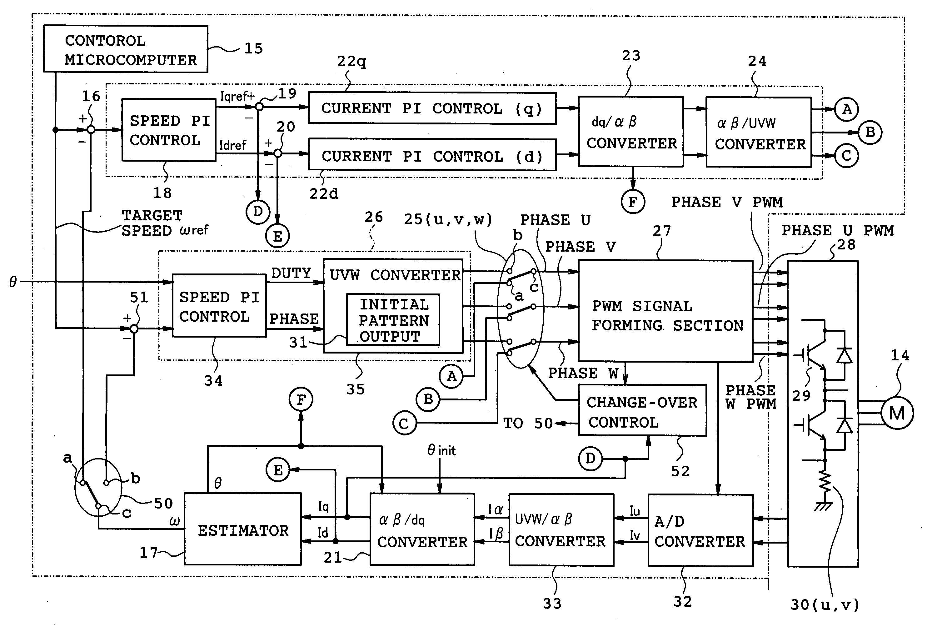
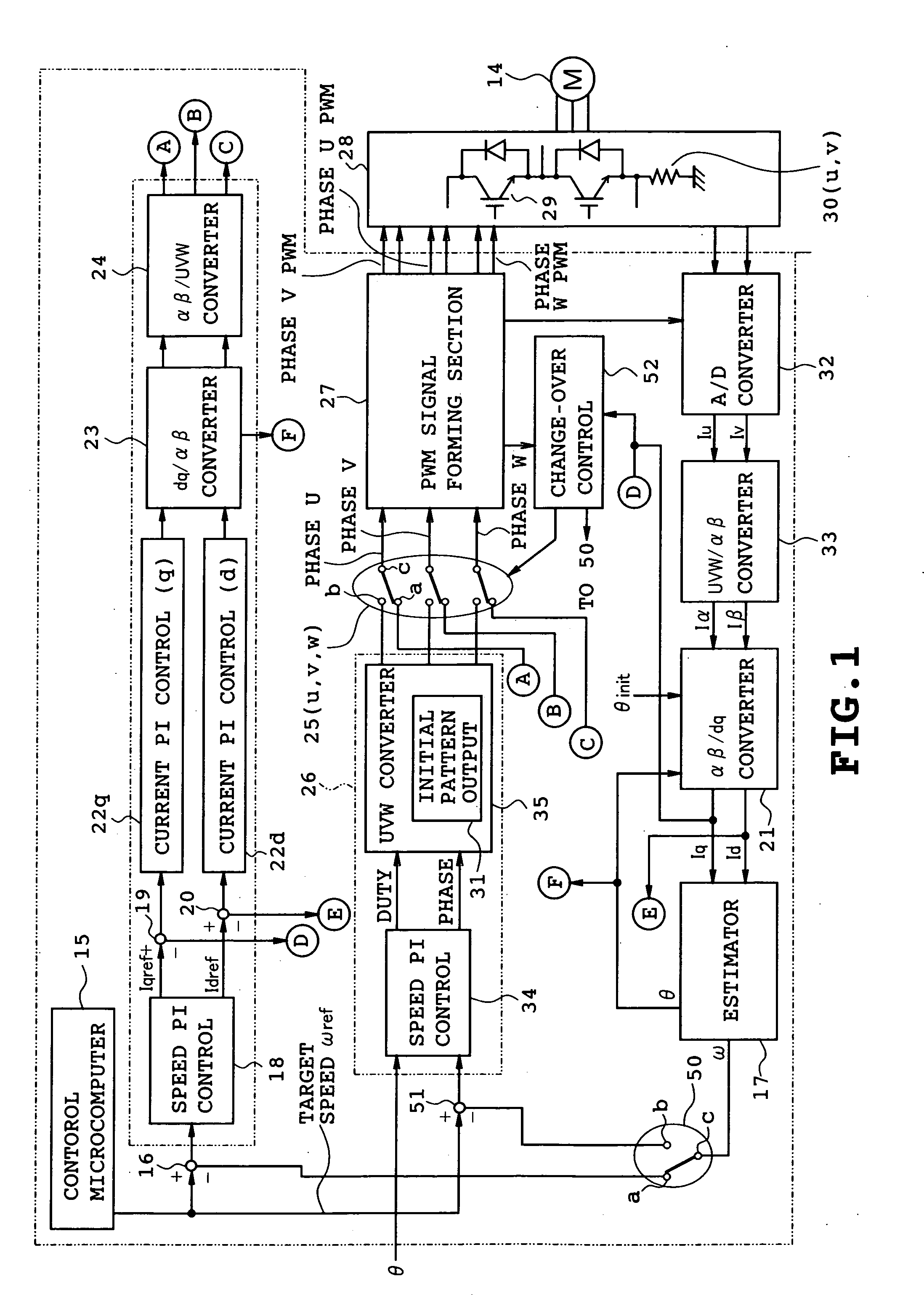
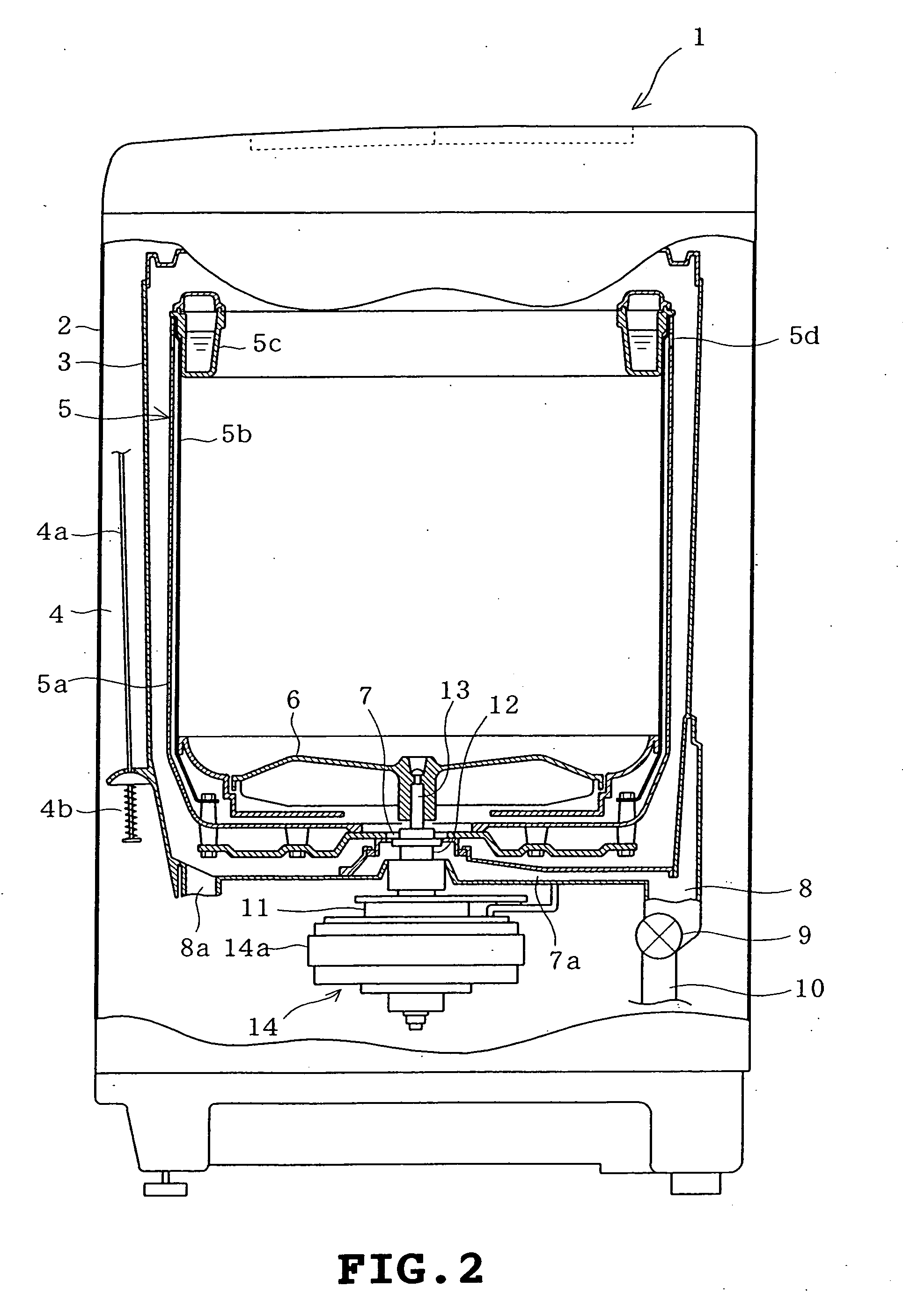
[0031] A first embodiment in which the present invention is applied to a vertical axis type full automatic washing machine will be described with reference to FIGS. 1 to 10. Firstly, FIG. 2 is a longitudinal section showing the overall washer. An outer cabinet 2 has a generally rectangular shape and a water-receiving tub 3 is elastically supported via four sets of vibration proofing mechanisms 4 (only one set is shown) in the water-receiving tub. Each set of vibration proofing mechanism 4 includes a suspension rod 4a having an upper end fixed to an upper portion of the cabinet 2 and the other end to which a vibration damper 4b is mounted. The water-receiving tub 3 is elastically supported via the vibration proofing mechanisms 4 such that the vibration produced in the washing operation is prevented from transmitting to the outer cabinet 2.

[0032] A rotating tub 5 serving both as a wash tub and as a dehydration tub is provided in the water-receiving tub 3. An agitator (pulsator) 6 is p...

third embodiment

[0097] FIGS. 17 to 20 illustrate a third embodiment in which the invention is applied to a washer-drier of the vertical axis type. FIG. 17 is a longitudinal section of the washer-drier. A lid 122 is provided for opening and closing the access opening through which laundry is put into and taken out of the rotating tub. The lid 122 is mounted on the central top of the body 121 constituting the outer shell. An operation panel 123 having various selecting switches is provided in the front of the body 121. A control device 124 (control means) controls the overall washing and drying operations and comprises a microcomputer-based circuit. The control device 124 is provided inside the body 121 so as to correspond to the operation panel 123.

[0098] A water tub 125 has an upper opening and is formed into the shape of a bottomed cylinder and can reserve water. The water tub 125 is mounted on a plurality of elastic supporting devices 126 (only one being shown) in the body 121. A drain hole 125a ...

second embodiment

[0100] The rotating tub 129 and the agitator 130 are driven by a drive motor 131 mounted on the underside of the water tub 125. In the washing operation, only the agitator 130 is driven via a clutch mechanism (not shown), whereas both agitator 130 and water tub 125 are driven in the dehydrating or drying operation. However, the water tub 125 is controlled so as to be rotated at a lower speed in the drying operation than in the dehydrating operation. The motor 131 comprises a brushless motor of the outer rotor type as in the first or

[0101] A warm air circulating passage 132 supplies warm air into the water tub 125 and is formed so as to extend from the lower end to the upper end of the water tub 125 at an inner corner of the body 121 and at one side of the water tub 125. The warm air circulating passage 132 has a lower end communicating through a duct 133a with the drain hole 125a formed in a lower portion of the water tub 125. The warm air circulating passage 132 has an upper end wh...


PUM


Abstract

An inverter for a washer performing drive control of an electric motor imparting a rotational driving force required for washing, rinsing and dehydrating operations in a full automatic washer performing the washing, rinsing and dehydrating processes continuously. The inverter comprises a control means for operating the motor with a full field in the low speed rotational region of washing, rinsing and dehydrating operations, with weak field in the high speed rotational region of dehydrating operation, and performing vector control of the output of the motor in the case of full field operation, and voltage/phase control of the motor in the case of field weakening operation.

Description

TECHNICAL FIELD [0001] The present invention relates to an inverter for a washer controlling an electric motor imparting a rotational driving force required for washing, rinsing and dehydrating operations with respect to an automatic washing machine in which steps of wash, rinse and dehydration are consecutively carried out, and an inverter for a washer-drier controlling an electric motor imparting a rotational driving force required for washing, rinsing and dehydrating operations with respect to an automatic washing machine in which steps of wash, rinse and dehydration are consecutively carried out. BACKGROUND ART [0002] In automatic washing machines, DC brushless motors have conventionally been used as motors for rotating a mixing blade (pulsator) or a rotating tub when washing, rinsing and dehydrating operations are carried out. A system for driving the DC brushless motors by an inverter circuit has been employed widely. Voltage applied to the motor is increased or decreased when...

Claims


Application Information

Patent Timeline
IPC IPC(8): D06F33/02D06F25/00D06F37/30H02P6/06H02P6/08H02P6/21H02P21/00H02P21/18H02P21/24H02P21/28H02P21/32H02P23/16H02P27/04H02P27/08
CPCD06F37/304Y02B40/52H02P21/00Y02B40/00D06F2103/24D06F2105/48D06F34/10
Inventor HOSOITO, TSUYOSHINAGAI, KAZUNOBU
Owner TOSHIBA LIFESTYLE PROD & SERVICES CORP
Why Eureka
Try Eureka