Engine cylinder liner construction

a technology for cylinders and cylinder gaskets, which is applied in the direction of cylinders, machines/engines, pistons, etc., can solve the problems of reducing cooling performance, reducing the accuracy of cylinder liners, and reducing sealing properties, so as to suppress the generation of damage to cylinder gaskets, and suppress the generation of cracks.

Active Publication Date: 2005-07-28
MITSUBISHI MOTORS CORP
View PDF9 Cites 12 Cited by
  • Summary
  • Abstract
  • Description
  • Claims
  • Application Information

AI Technical Summary

Benefits of technology

[0010] The invention was made based on the problem, and a primary object thereof is to provide an engine cylinder liner construction which can suppress the generation of a crack in the vicinity of an end portion of a joint portion between the casting portion of the cylinder block and the cylinder liner having spines to thereby prevent the reduction in sealing properties of combustion gases. A secondary object of the invention is to provide an engine cylinder liner construction which can ensure the suppression of the generation of a crack in the vicinity of an extended portion on a cylinder block main body side to thereby prevent the reduction in sealing properties due to a damage to a cylinder gasket when applied to a cylinder block into which a cylinder liner having projections is cast while an end portion of the cylinder liner which faces the cylinder head is covered with the extended portion from the cylinder head side.
[0015] According to the first aspect of the invention, since the chamfered portion is formed at the end portion of the tubular portion positioned in the vicinity of the end portion of the joint portion between the cylinder block and the cylinder liner or positioned on the cylinder head side by chamfering the end portion together with the spines located thereat in a tapered fashion, the spines located in the vicinity of the end portion of the joint portion can be removed so as to suppress the generation of a crack from the spines to thereby suppress the generation of damage to the cylinder gasket due to a crack that would otherwise be generated, thereby making it possible to ensure the prevention of reduction in sealing properties between the cylinder block and the cylinder head.
[0016] According to the second aspect of the invention, since the chamfered portion is formed at the end portion of the tubular portion positioned in the vicinity of the end portion of the joint portion between the cylinder block and the cylinder liner or positioned on the cylinder head side by chamfering the end portion together with the spines located thereat in a tapered fashion, the spines located in the vicinity of the extended portion which covers the end portion of the cylinder liner which faces the cylinder head can be removed so as to suppress the generation of a crack from the spines in the vicinity of the extended portion to thereby suppress the generation of damage to the cylinder gasket due to a crack that would otherwise be generated, thereby making it possible to ensure the prevention of reduction in sealing properties between the cylinder block and the cylinder head.
[0017] According to the third aspect of the invention, since the angle of inclination of the chamfered portion formed at the end portion of the tubular portion is set to be about 12° to 30°, when the fastening load, which varies to be increased or decreased in accordance with a variation in the gas pressure, is applied to the chamfered portion via the extended portion, a component of the fastening load which is divided in a radial direction of a cylinder is suppressed to thereby suppress, in turn, an inclined displacement of the end portion of the joint portion of the tubular portion to the cylinder block into the interior of the cylinder, and moreover, since the spines are cut within a range where a cut with of the chamfered portion in an axial direction of the cylinder does not become too large, the reduction in adhesion properties between the tubular portion and the cylinder block can be prevented.
[0018] According to the fourth aspect of the invention, since the chamfered portion and the end face of the tubular portion which faces the cylinder head are rounded so as to eliminate any edge-like shape thereat, the generation of a crack in the extended portion in the vicinity of the rounded overlapping portion R can be prevented in an ensured fashion, and in particular, together with the advantage of the formation of the chamfered portion at the end portion of the tubular portion which faces the cylinder head by chamfering the eng portion together with the spines located thereat, the generation of a crack in the vicinity of the end portion of the joint portion between the tubular portion and the cylinder block-can be prevented in a more ensured fashion.

Problems solved by technology

Incidentally, in a case where the casting process is adopted to produce engines in which cylinder liners are cast into a cylinder block, when casting cylinder liners made of a different material into the cylinder block, due to the difficulty in making the cylinder block to completely adhere to the cylinder liners at the time of producing a cylinder block main body, minute gaps are produced between the cylinder block and the cylinder liners with time, and there are caused problems of reduction in accuracy of the roundness of the cylinder liner and of reduction in cooling performance thereof.
Moreover, a crack 170 tends to be easily produced in a distal end of a needle-like projection 180 which is formed in the vicinity of the end portion of the cylinder liner 110 which faces the cylinder head 120 in association with the concentration of stress thereat, and this tends to produce a damaged portion C in a portion of the gasket 130 which faces the cracks so produced in the end portion of the cylinder liner 110, resulting in an easy-occurring problem that the sealing properties are reduced.

Method used


Image

  • Engine cylinder liner construction
  • Engine cylinder liner construction
  • Engine cylinder liner construction

Examples


Embodiment Construction

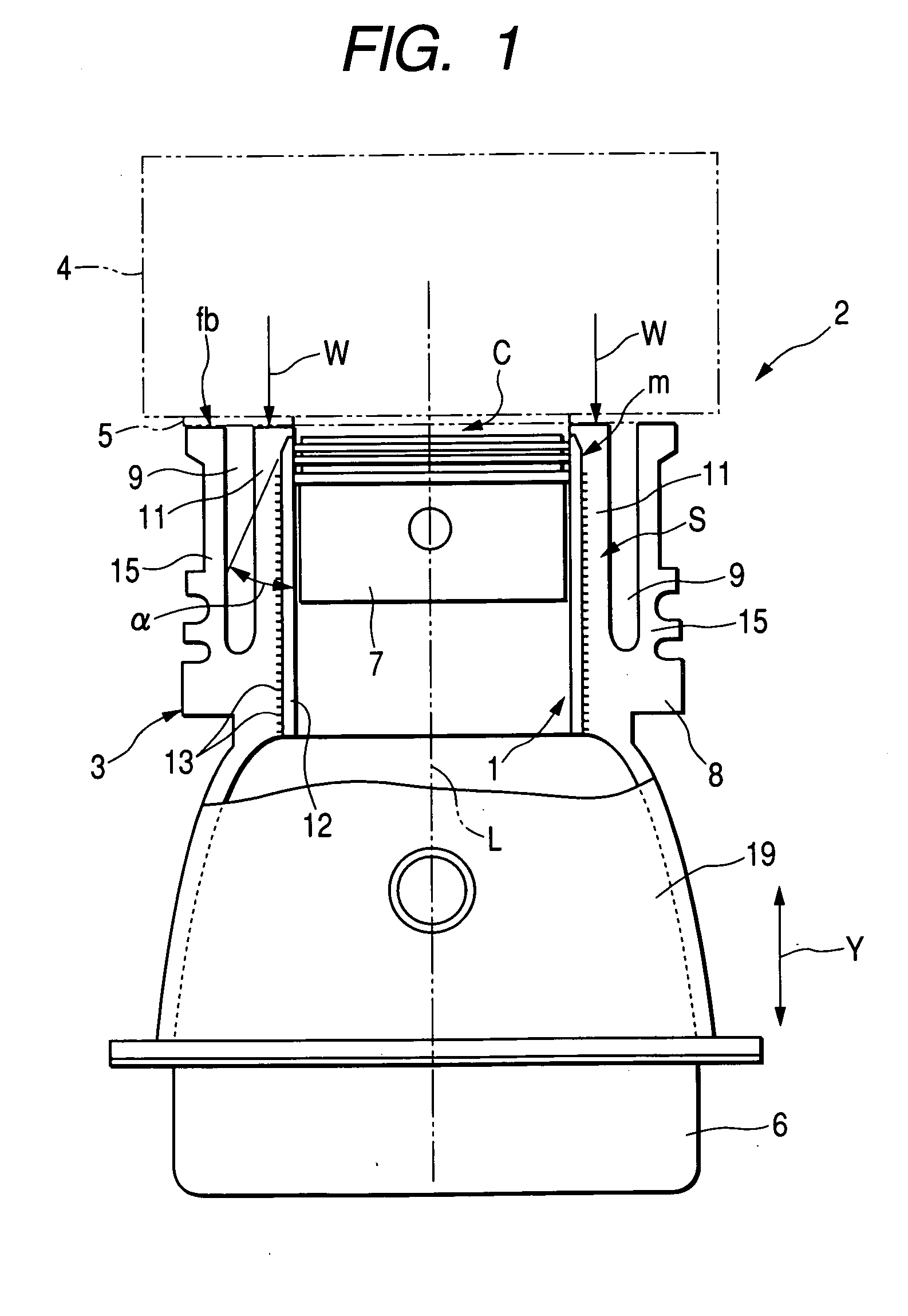
[0025] A gasoline engine (hereinafter, simply referred to as an engine) 2 adopting a cylinder block to which the a cylinder liner construction as an embodiment of the invention is applied is shown in FIG. 1.

[0026] A main body of the engine 2 has a cylinder block 3 into which a cylinder liner 1 is cast, a cylinder head 4 and a head cover, not shown, which are sequentially connected together to an upper side of the cylinder block 3 in that order and an oil pan 6 which is integrally connected to a lower side of the cylinder block 3. The engine 2 is a multi-cylinder engine having a plurality of cylinders S which are formed into the same configuration, a piston 7 is disposed in each cylinder S in such a manner as to slide vertically, and a combustion chamber is defined by the cylinder liner 1, the piston 7 and a lower wall of the cylinder head 4 in such a manner that the capacity thereof can be changed.

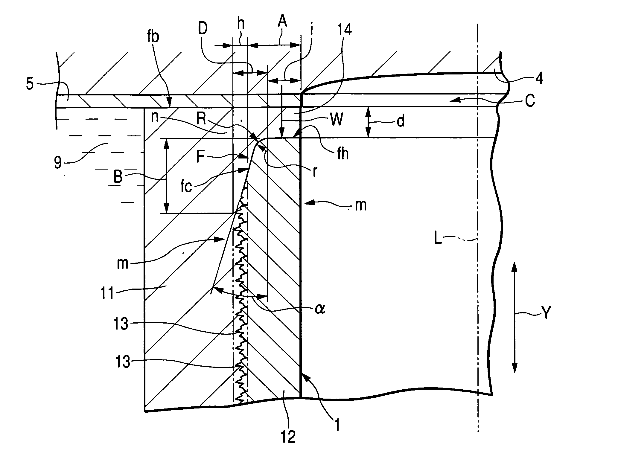
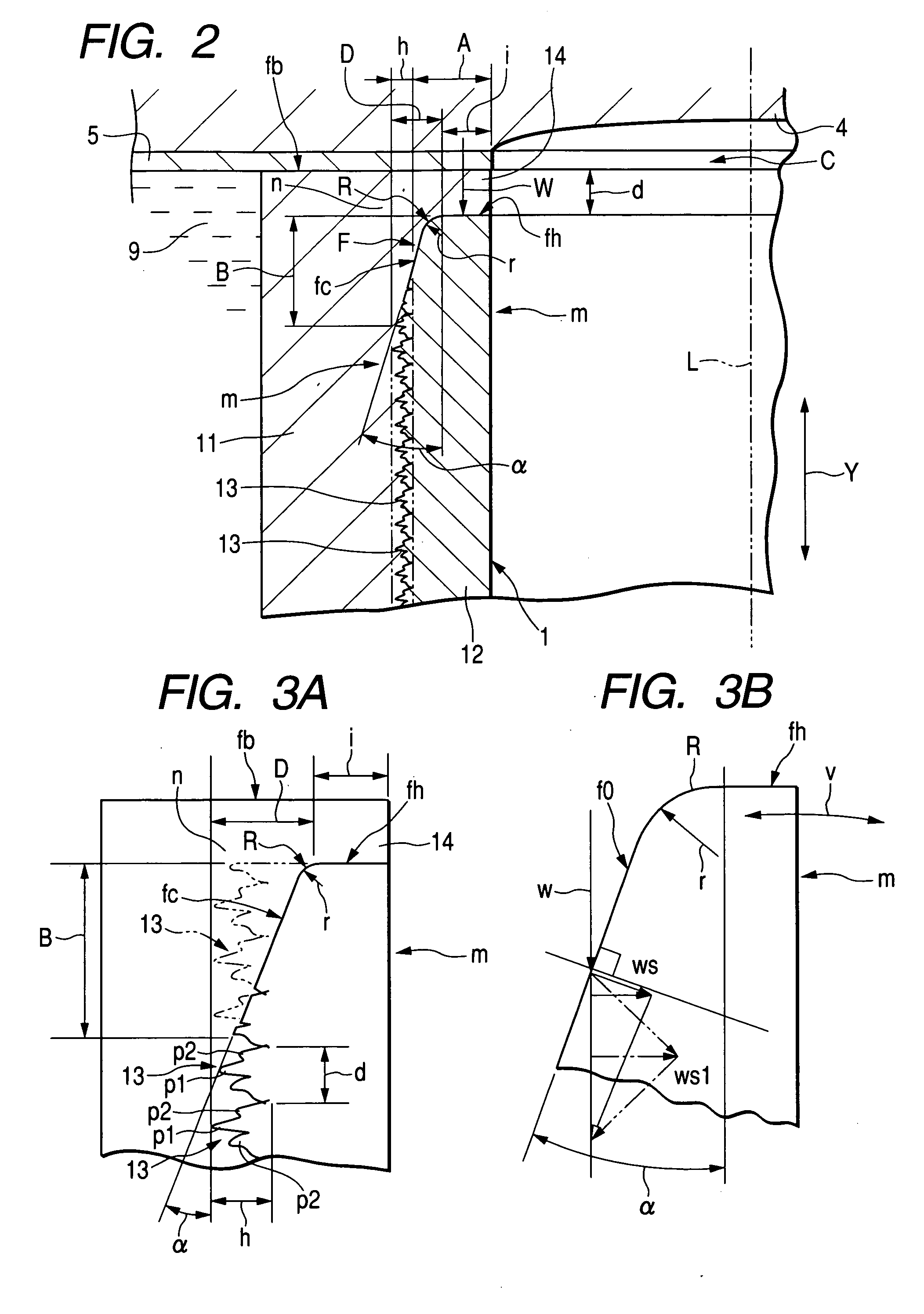
[0027] A gasket 5 is disposed between the cylinder block 3 and the cylinder head 4, ...


PUM

PropertyMeasurementUnit
angle of inclinationaaaaaaaaaa

Abstract

An engine cylinder liner construction in which a cylinder liner that is cast into a cylinder block has a tubular portion and a number of spines integrally formed on an outer surface of the tubular portion, the engine cylinder liner construction being characterized in that a chamfered portion is formed at an end portion m of the tubular portion which faces a cylinder head by chamfering the end portion together with the spines located thereat in a tapered fashion.

Description

CROSS REFERENCE TO RELATED APPLICATION [0001] This non-provisional application incorporates by reference the subject matter of Application No. 2003-431207 filed in Japan on Dec. 25, 2004, on which a priority claim is based under 35 U.S.C. §119(a). BACKGROUND OF THE INVENTION [0002] 1. Field of the Invention [0003] The present invention relates to an engine cylinder liner construction in which a cylinder liner is cast into a cylinder block, and more particularly to an engine cylinder liner construction in which projections are formed on an outer surface of the cylinder liner so as to strengthen the adhesion properties of the cylinder liner to the cylinder block. [0004] 2. Description of the Related Art [0005] There have been adopted lots of engines in which a cylinder block main body is made of aluminum alloy with a view to reducing the weight thereof. Incidentally, in the aluminum alloy-made cylinder block of this type, in many cases, separate cylinder liners of cast iron or steel a...

Claims


Application Information

Patent Timeline
Patent Type & Authority Applications(United States)
IPC IPC(8): B22D19/00B22D19/08F02F1/00F02F1/10F02F1/18F16J10/00F16J10/04
CPCB22D19/0009F02F1/18F02F1/102
Inventor KOMAI, HIROKAZUHASEGAWA, TAKESHI
Owner MITSUBISHI MOTORS CORP
Why Eureka
Try Eureka