Direct fuel injection/spark ignition engine control device

a technology of control device and spark ignition engine, which is applied in the direction of electric control, machines/engines, mechanical equipment, etc., can solve the problems of weakening compression stroke, contributing to an increase in flame propagation velocity at the atdc ignition, and reducing hc, increasing exhaust temperature, and improving combustion stability in the atdc ignition

Inactive Publication Date: 2005-07-28
NISSAN MOTOR CO LTD
View PDF7 Cites 17 Cited by
  • Summary
  • Abstract
  • Description
  • Claims
  • Application Information

AI Technical Summary

Benefits of technology

[0009] For this reason, the ATDC ignition is more effective in reducing HC and increasing the exhaust temperature. However, since combustion is not stabilized, the BTDC ignition is used in the no-load range as in the fuel injection control system of Japanese

Problems solved by technology

In Japanese Patent No. 3325230, however, the first fuel injection (early-stage injection) is principally carried out in the intake stroke and the second fuel injection (later-stage injection) is carried out at 120 to 45° BTDC in the compression stroke, and even if turbulence is generated in the cylinder by the spray from the first fuel injection (e

Method used


Image

  • Direct fuel injection/spark ignition engine control device
  • Direct fuel injection/spark ignition engine control device
  • Direct fuel injection/spark ignition engine control device

Examples


Embodiment Construction

[0018] Selected embodiments of the present invention will now be explained with reference to the drawings. It will be apparent to those skilled in the art from this disclosure that the following descriptions of the embodiments of the present invention are provided for illustration only and not for the purpose of limiting the invention as defined by the appended claims and their equivalents.

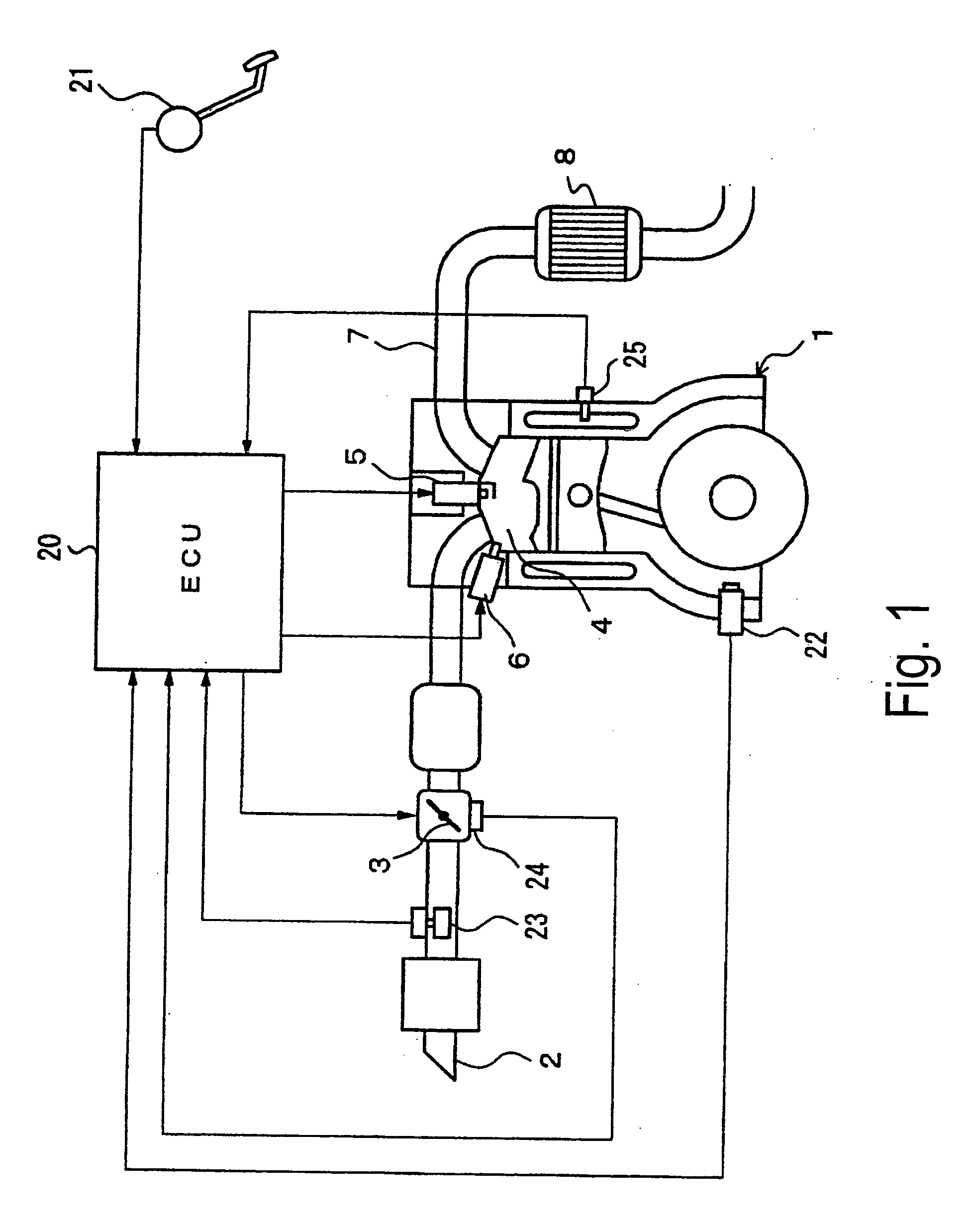
[0019] Referring initially to FIG. 1, a direct fuel injection / spark ignition internal combustion engine 1 is diagrammatically illustrated that is equipped with a direct fuel injection / spark ignition engine control device in accordance with the present invention. The engine 1 has an intake passage 2 with an electronically controlled throttle valve 3 mounted therein. The electronically controlled throttle valve 3 is configured and arranged for controlling the intake air quantity to the intake passage 2 of the engine 1. The intake passage 2 is fluidly connected to a plurality of combustion chambers ...


PUM


Abstract

A control apparatus is configured to enhance turbulence in the cylinder produced by the fuel spray, and to improve combustion stability (promote flame propagation) in an ATDC designed to reduce HC and/or achieve early activation of the catalyst. Ignition timing is set to compression top dead center or later when for example the catalyst requires warming. In one fuel injection timing, a single fuel injection is injected prior to ignition timing at compression stroke top dead center or later. Alternatively, the fuel is injected in two fuel injections with a first fuel injection occurring during either the intake stroke or the compression stroke and the second fuel injection occurring at compression stroke top dead center or later.

Description

CROSS-REFERENCE TO RELATED APPLICATIONS [0001] This application claims priority to Japanese Patent Application Nos. 2004-20083 and 2004-20085. The entire disclosures of Japanese Patent Application Nos. 2004-20083 and 2004-20085 are hereby incorporated herein by reference. BACKGROUND OF THE INVENTION [0002] 1. Field of the Invention [0003] The present invention generally relates to a control device for a direct fuel injection spark ignition engine. More specifically, the present invention relates to a control device that is suitable during cold starting and the other times, or when it is necessary to warm up a catalyst for exhaust purification provided to the exhaust channel. [0004] 2. Background Information [0005] One example of a direct fuel injection spark ignition engine with a fuel injection control is disclosed in Japanese Patent No. 3325230. This patent discloses a fuel injection control that is applied when the catalytic converter is in an un-warmed state, i.e., when the temp...

Claims


Application Information

Patent Timeline
IPC IPC(8): F02D37/02F02D41/02F02D41/30F02D41/40
CPCF02D37/02F02D41/401F02D2041/389F02D41/403F02D41/402
Inventor TOMITA, MASAYUKI
Owner NISSAN MOTOR CO LTD
Why Eureka
Try Eureka