
Direct fuel injection/spark ignition engine control device

a technology of control device and internal combustion engine, which is applied in the direction of electric control, machines/engines, liquid fuel feeders, etc., can solve the problems of inability to achieve adequate delay of ignition timing and difficulty in ensuring stable combustion, so as to improve combustion stability in atdc ignition and reduce hc

Active Publication Date: 2006-09-12
NISSAN MOTOR CO LTD
View PDF15 Cites 0 Cited by
  • Summary
  • Abstract
  • Description
  • Claims
  • Application Information

AI Technical Summary

Benefits of technology

The present invention is a control device for a direct fuel injection / spark ignition engine that improves combustion stability to reduce HC and increase the temperature of the exhaust gas for early activation of the catalyst when the engine is cold. The control device includes a fuel injection control section and an ignition timing control section. The fuel injection control section controls fuel injections during a period that straddles over the compression top dead center, while the ignition timing control section controls sparking of a spark plug to ignite fuel at or after the compression top dead center. This results in improved combustion stability and reduced HC.

Problems solved by technology

However, since combustion stability worsens when the ignition timing is considerably delayed, the ignition timing cannot be delayed beyond a certain limit, which is determined based on considerations related to combustion stability.
In the above-described prior art, it is difficult to ensure stable combustion under conditions such as when the engine is cold in particular, the delay limit of the ignition timing that is determined based on combustion stability is relatively advanced, and adequate delay of the ignition timing cannot be achieved.

Method used


Image

  • Direct fuel injection/spark ignition engine control device
  • Direct fuel injection/spark ignition engine control device
  • Direct fuel injection/spark ignition engine control device

Examples


Embodiment Construction

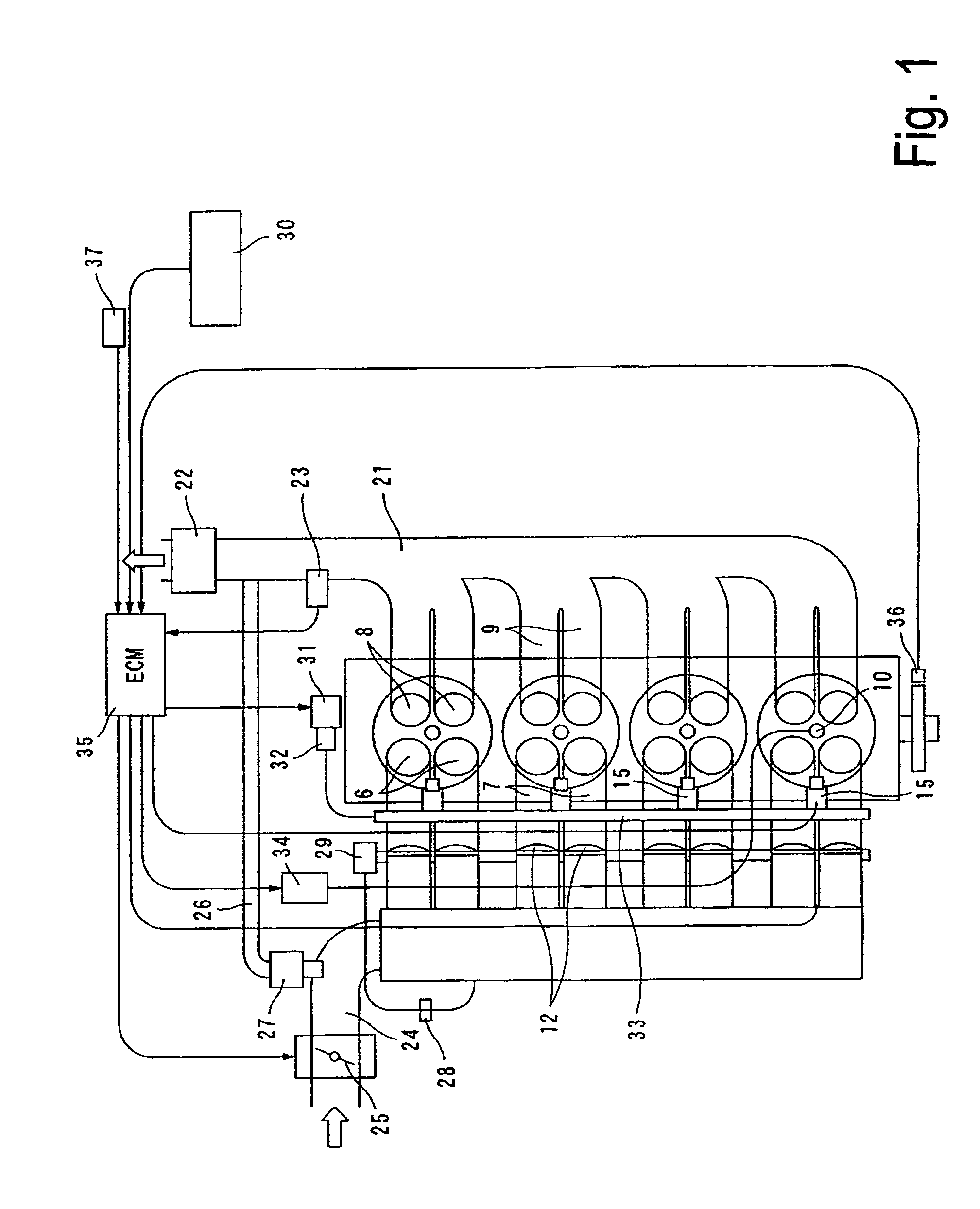
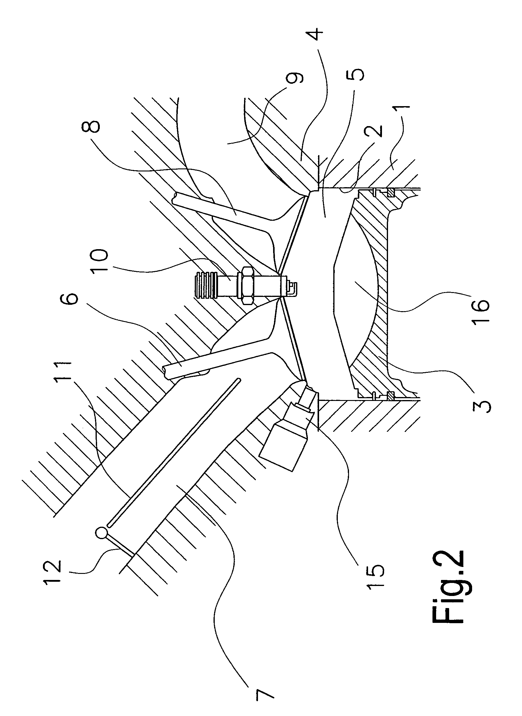
[0029]Selected embodiments of the present invention will now be explained with reference to the drawings. It will be apparent to those skilled in the art from this disclosure that the following descriptions of the embodiments of the present invention are provided for illustration only and not for the purpose of limiting the invention as defined by the appended claims and their equivalents.

[0030]Referring initially to FIGS. 1 to 3, a direct fuel injection / spark ignition internal combustion engine is diagrammatically illustrated that is equipped with a direct fuel injection / spark ignition engine control device in accordance with a first embodiment of the present invention. The internal combustion engine of this embodiment is, for example, an inline four-cylinder engine. The engine basically includes a cylinder block 1 with a plurality of a cylinders 2, a plurality of pistons 3 slidably disposed in the cylinders 2 and a cylinder head 4 fixed to upper surface of the cylinder block 1. Th...


PUM


Abstract

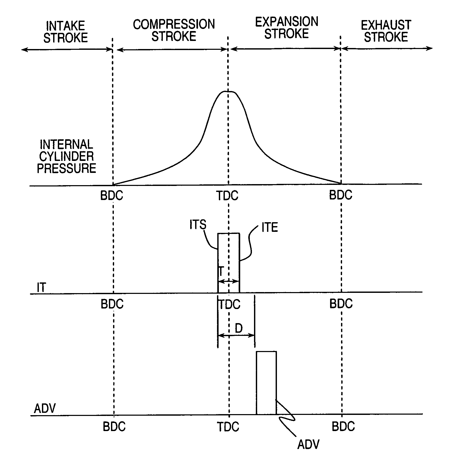
A control apparatus is configured to achieve considerably delayed ignition timing and combustion stability, and to bring about an increase in exhaust gas temperature and a reduction in HC discharge when the engine is cold. Normal stratified combustion operation and homogeneous combustion operation are carried out when warming has been completed and the coolant temperature of the internal combustion engine has exceeded 80° C. In an injection operation at the top dead center, the injection start timing ITS occurs prior to compression top dead center (TDC) and the injection end timing ITE occurs after compression top dead center (TDC), whereby fuel injection is carried out so as to straddle the compression top dead center. The ignition timing ADV occurs after compression top dead center (TDC) and ignition occurs with a timing that is delayed from the injection start timing ITS.

Description

CROSS-REFERENCE TO RELATED APPLICATIONS[0001]This application claims priority to Japanese Patent Application Nos. 2004-020085 and 2004-197533. The entire disclosures of Japanese Patent Application Nos. 2004-020085 and 2004-197533 are hereby incorporated herein by reference.BACKGROUND OF THE INVENTION[0002]1. Field of the Invention[0003]This present invention relates to a control apparatus for a direct-injection spark-ignition internal combustion engine for directly injecting fuel into the cylinder, and more specifically relates to control of the injection timing and ignition timing.[0004]2. Background Information[0005]Japanese Laid-Open Patent Application No. 2000-45843 discloses a technique for dividing an entire fuel injection amount into an early injection and a later injection. The early injection occurs during the intake stroke and the later injection occurs during the compression stroke, with the ignition timing being delay beyond the point of MBT when the catalytic converter ...

Claims


Application Information

Patent Timeline
Patent Type & Authority Patents(United States)
IPC IPC(8): F02B5/00F02D37/02F02D41/02F02D41/30F02D41/40
CPCF02D37/02F02D41/405F02D41/401Y02T10/44F02D2041/389Y02T10/40
Inventor ISHII, HITOSHITOMITA, MASAYUKIKONO, TOSHIYA
Owner NISSAN MOTOR CO LTD
Learn More