
Liquid absorbing filter assembly and system using same

a filter assembly and liquid absorbing technology, applied in the field of sidestream gas monitoring system, can solve the problems of condensed liquid, inaccurate monitoring, and detriment to the functioning of the system,

Active Publication Date: 2005-07-28
PHILIPS RS NORTH AMERICA LLC
View PDF11 Cites 90 Cited by
  • Summary
  • Abstract
  • Description
  • Claims
  • Application Information

AI Technical Summary

Benefits of technology

[0012] Accordingly, it is an object of the present invention to provide a filter assembly that overcomes the shortcomings of conventional filter assemblies. This object is achieved according to one embodiment of the present invention by providing a low deadspace filter assembly for use in sidestream gas sampling system that includes a housing lined along the inner wall thereof with a hydrophilic liner for wicking moisture out of the expired gases. In one embodiment, the hydrophilic liner lines the inner perimeter of the cylindrical housing substantially along its entire axial length, excepting a portion at the downstream-most end thereof where a hydrophobic member and an exit conduit are located. The hydrophobic member extends across the inner diameter of the channel through cylindrical housing near the downstream end thereof. The housing is adapted to be coupled in a gas-tight and fluid-tight arrangement with a gas sampling line through which expired gases may be received.
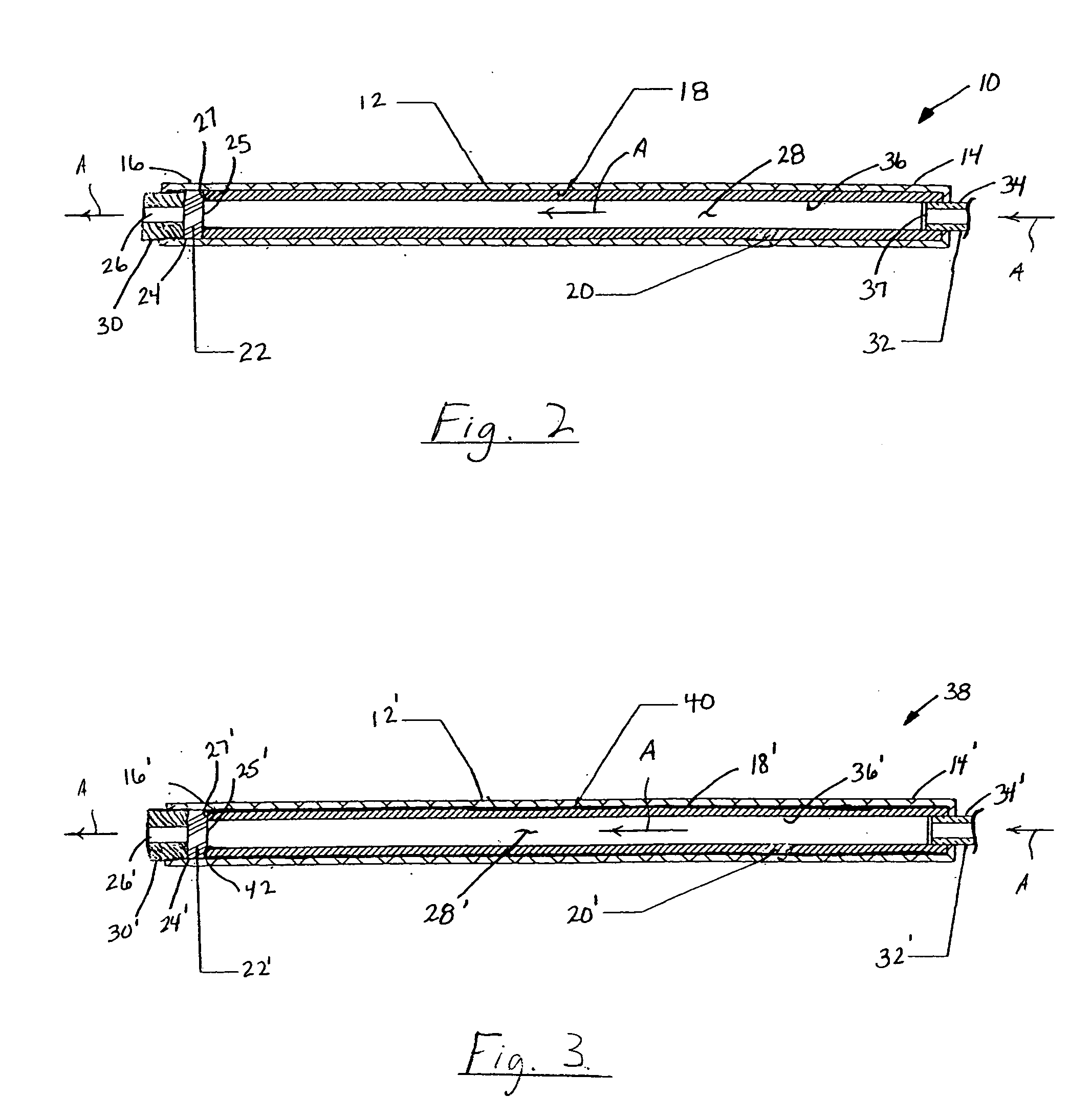
[0014] In an alternative embodiment, the filter assembly of the present invention further includes an absorbent layer positioned between the inner perimeter of the cylindrical housing and the hydrophilic liner. The absorbent material has a higher absorbance than the hydrophilic layer and further aids in wicking moisture from the expired gases and locking it away from the gases to be monitored.

Problems solved by technology

The liquid, i.e., condensate, if permitted to reach the sensing mechanism, can have a detrimental effect on the functioning thereof and may lead to inaccurate monitoring results.
Condensed liquid in the gas sampling line may also contaminate subsequent expired gas samples by being re-entrained into such subsequent samples.
Each of these liquids, if present in the gas sample to be monitored, may render analytical results that do not accurately reflect the patient's medical status.
The challenge, however, is to achieve the separation without affecting the characteristics of the parameters being measured, e.g., the waveform of the gas to be monitored.
Disturbances in this fluctuation, i.e., in the CO2 waveform, are undesirable because any such disturbance can affect the accuracy of the CO2 measurement and the graphical display of the waveform.
Unfortunately, conventional moisture traps often disturb the waveform to a substantial degree.
While each of these techniques has its advantages, each has its drawbacks as well.
Each of the techniques listed above can remove a portion of the liquid condensate, but none is foolproof, except, perhaps for those using a hydrophobic filter.
On the other hand, conventional filters that use a hydrophobic filter, can disturb the waveform beyond acceptable levels.

Method used


Image

  • Liquid absorbing filter assembly and system using same
  • Liquid absorbing filter assembly and system using same
  • Liquid absorbing filter assembly and system using same

Examples


first embodiment

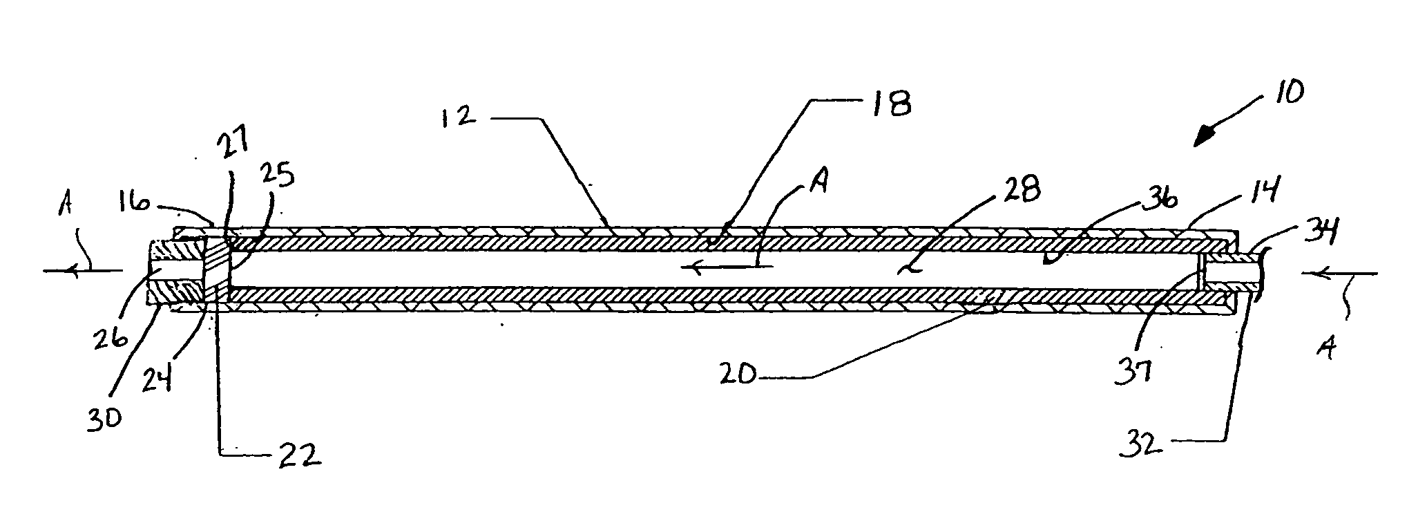
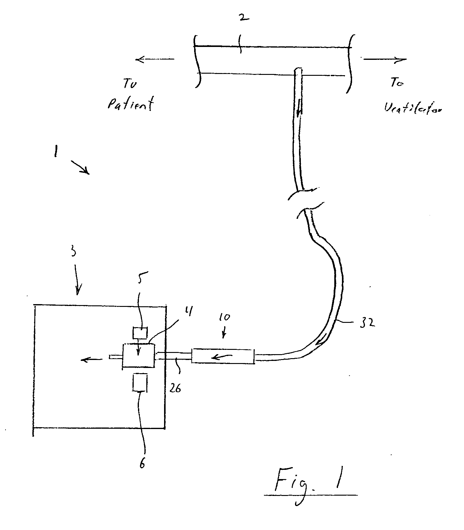
[0027] Referring now to FIG. 2, which is 2 is a cross-sectional view of filter assembly 10, the filter assembly includes a housing 12 typically formed of a suitable polymer and having a cylindrical shape. Of course, other materials and shapes are contemplated by the present invention. Housing 12 includes axially opposed first and second ends 14, 16 and has an inner diameter defined by an inner wall 18 thereof. During normal use, gas is carried from the patient circuit into first end 14 via a sampling line 32 connected to the first end. The gas passes through a channel 28 defined in housing 12 and exits second end 16, where it is provided to gas monitoring system 3 of FIG. 1. The flow of gas through filter assembly 10 is indicated by arrows A.

[0028] Lining inner wall 18 of housing 12 is a hydrophilic liner 20 for wicking moisture from expired gases and locking it away from the gas stream, as more fully described below. The present invention contemplates that hydrophilic liner 20 be f...

second embodiment

[0037] Referring now to FIG. 3, a filter assembly according to the principles of the present invention is illustrated and denoted generally by, reference numeral 38. Like filter assembly 10 of FIG. 2, filter assembly 38 includes a housing 12′ typically formed of a suitable polymer and having a cylindrical shape. Housing 12′ has axially opposed first and second ends 14′, 16′ and an inner diameter defined by an inner wall 18′ thereof. Lining inner wall 18′ is a hydrophilic liner 20′ for wicking moisture from expired gases and locking it away from the gas stream. The present invention contemplates that hydrophilic liner 20′ be formed of a material suitable for accomplishing the wicking function, such as a porous plastic, having a pore size ranging from approximately 5 microns to approximately 50 microns. As discussed above, hydrophilic liner 20′ not only absorbs moisture but also acts as a smooth lining for housing 12′, and thereby minimizes the turbulence effects on the gas stream cau...

third embodiment

[0046]FIG. 4 is a cross-sectional view of a portion of the filter assembly 50 according to the principles of the present invention. Filter assembly 50 includes a housing 52 connected to a sampling line 32 and to a exit sampling line 33. A hydrophilic member 54 is disposed in the housing between sampling line 32 and housing 52. A hydrophobic member 56 is provided across the diameter of the housing. Sealing elements 58 are provided at each end of the housing to connect the housing the inlet and outlet lines. Housing 52 can be made from any suitable material, such as plastic, rubber, or silicon. The present invention also contemplates that the housing can be formed, at least in part, from an absorbent material or a gas drying material that is able to remove water / fluid from the gas, such as NAFION® produced by DuPont.

[0047] The filter assembly of this embodiment is generally similar to that shown in FIG. 2, except that hydrophilic member 54 is disposed between sampling line 32 and the ...


PUM


Abstract

A filter assembly for use in sidestream gas sampling assembly. The filter assembly of the present invention includes a hydrophilic liner lining the inner perimeter of a housing for wicking moisture from the gases to be monitored prior to the gases reaching a sensing mechanism. The filter further includes a hydrophobic member positioned downstream of the hydrophilic liner. The hydrophobic disk acts as a second line of defense against moisture reaching the sensing mechanism. In one embodiment, the filter further include an absorbent layer positioned between the cylindrical housing and the hydrophilic layer to aid in wicking moisture from the gas stream. In a further embodiment, the hydrophobic disk is eliminated and the hydrophilic member is situated such that gas entering the filter assembly must pass through at least a portion the hydrophilic member.

Description

CROSS-REFERENCE TO RELATED APPLICATIONS [0001] [Ol] This application claims priority under 35 U.S.C. § 119(e) from provisional U.S. patent application No. 60 / 538,766 filed Jan. 23, 2004 the contents of which are incorporated herein by reference.BACKGROUND OF THE INVENTION [0002] 1. Field of the Invention [0003] The present invention relates generally to a sidestream gas monitoring system for monitoring a patient's medical condition, and, in particular, to a filter assembly for use in a sidestream monitoring system that separates undesired liquid components from respiratory gases to be monitored. [0004] 2. Description of the Related Art [0005] During medical treatment, it is often desirable to monitor and analyze a patient's exhalations to determine the gaseous composition of the exhalate. For instance, monitoring the carbon dioxide (CO2) content of a patient's exhalations is often desirable. Typically, the carbon dioxide (or other gaseous) content of a patient's exhalation is monito...

Claims


Application Information

Patent Timeline
Patent Type & Authority Applications(United States)
IPC IPC(8): A61B5/097
CPCA61M2230/432A61B5/097A61M16/085
Inventor FUDGE, BRIAN M.TRIUNFO, JOHN A. JR.RICH, DAVID R.
Owner PHILIPS RS NORTH AMERICA LLC
Learn More