Method of cleaning hole diggers and spot cultivators and hole digger cleaning device

a technology of cleaning device and cultivator, which is applied in the direction of mechanical machines/dredgers, spades, applications, etc., can solve the problem of hard cleaning

Inactive Publication Date: 2005-07-28
MANOR GEDALYAHU
View PDF6 Cites 21 Cited by
  • Summary
  • Abstract
  • Description
  • Claims
  • Application Information

AI Technical Summary

Benefits of technology

[0009] In another preferred embodiment the rotating shafts are covered by stationary covering sleeves. The stationary covering sleeves are mounted on the main gearbox of the post hole digger or the rolling spot cultivator. On the other side the sleeves are connected to bearing housings on the end of the shafts. The bearings allow the cultivator shafts and blades to rotate and cultivate the soil while the sleeves prevent the build-up of mud and debris around the shafts above the blades. The cultivating blades are mounted to the shafts and secured, preferable by pins or bolts.
[0010] In another preferred embodiment the lower cultivating blades are rotating in the opposite direction to the upper portion of the digger, which has the auger flights or the upper set of cultivating blades. The counter rotating blades cut the debris and prevents them from accumulating with mud on the blades and the shaft between them. The driving pinion in the main gearbox is rotating two gears, one of them in one direction, and the other one in the counter direction. One of the gear wheels is connected to hollow shaft and rotates it in one direction, and the other gear wheel is connected to an inner shaft and rotates it to the counter direction The digger's hollow shaft is mounted to the hollow shaft of the gearbox by flanges (as an example) to rotate with it. The upper set of blades or auger flights is mounted to the hollow shaft by hollow pins, or bolts, around it, or welded to it, and rotates with it in one direction. The inner shaft of the digger is mounted to the inner shaft of the gearbox and rotates with it in the counter direction. The lower set of blades is mounted to the inner shaft of the digger and rotates with it in the counter direction to the upper set of blades or flights. The counter rotating blades prevent the mud and debris from accumulating between the blades. The stationary sleeve is mounted to the main gearbox and connected at its other lower end to the bearing housing on the hollow shaft of the digger to prevent the accumulation of mud and debris on the hollow shaft.

Problems solved by technology

The combination of mud with the string-like debris makes it very hard to clean, unless it is being cleaned immediately after digging each hole.

Method used


Image

  • Method of cleaning hole diggers and spot cultivators and hole digger cleaning device
  • Method of cleaning hole diggers and spot cultivators and hole digger cleaning device
  • Method of cleaning hole diggers and spot cultivators and hole digger cleaning device

Examples


Embodiment Construction

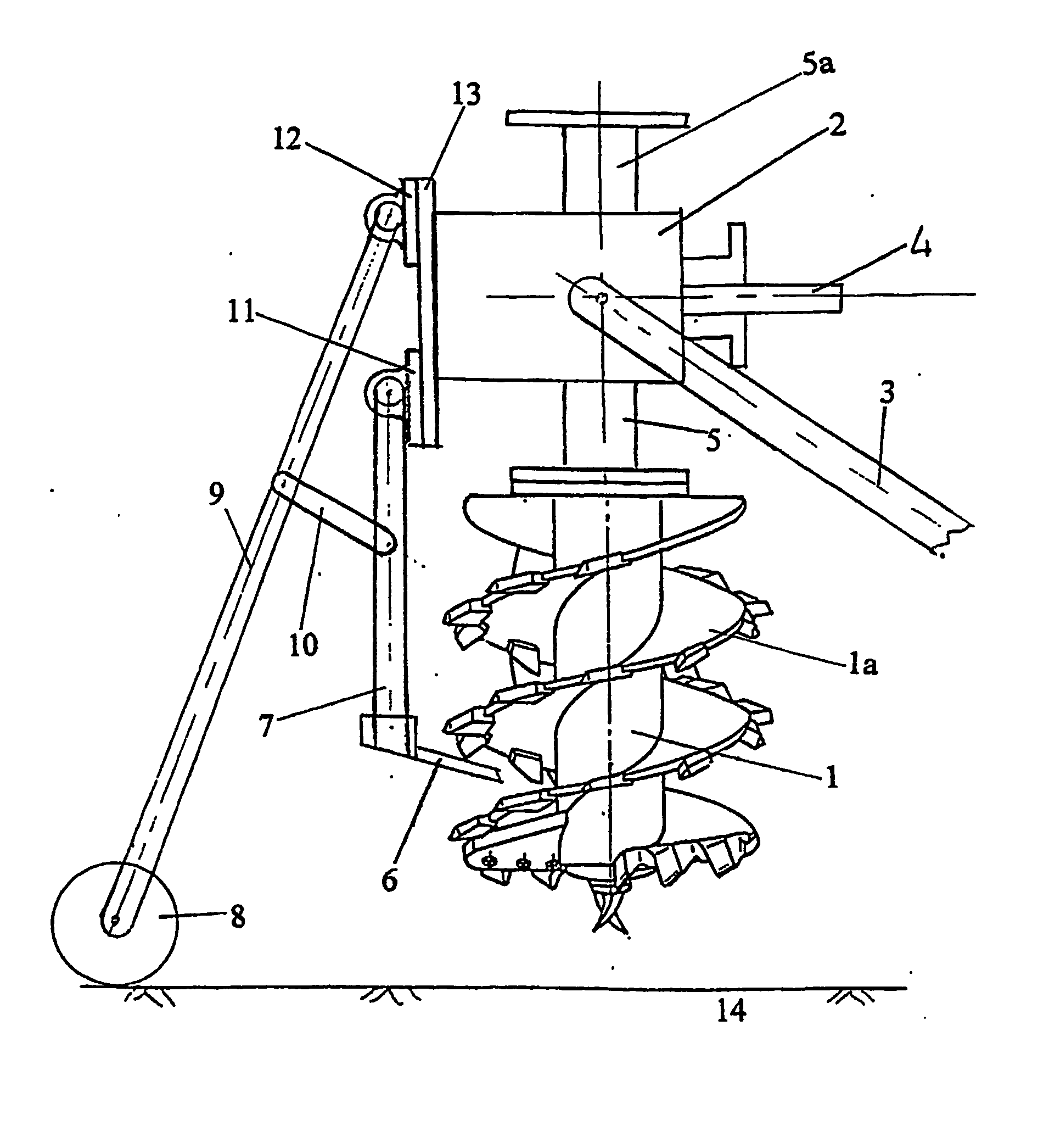
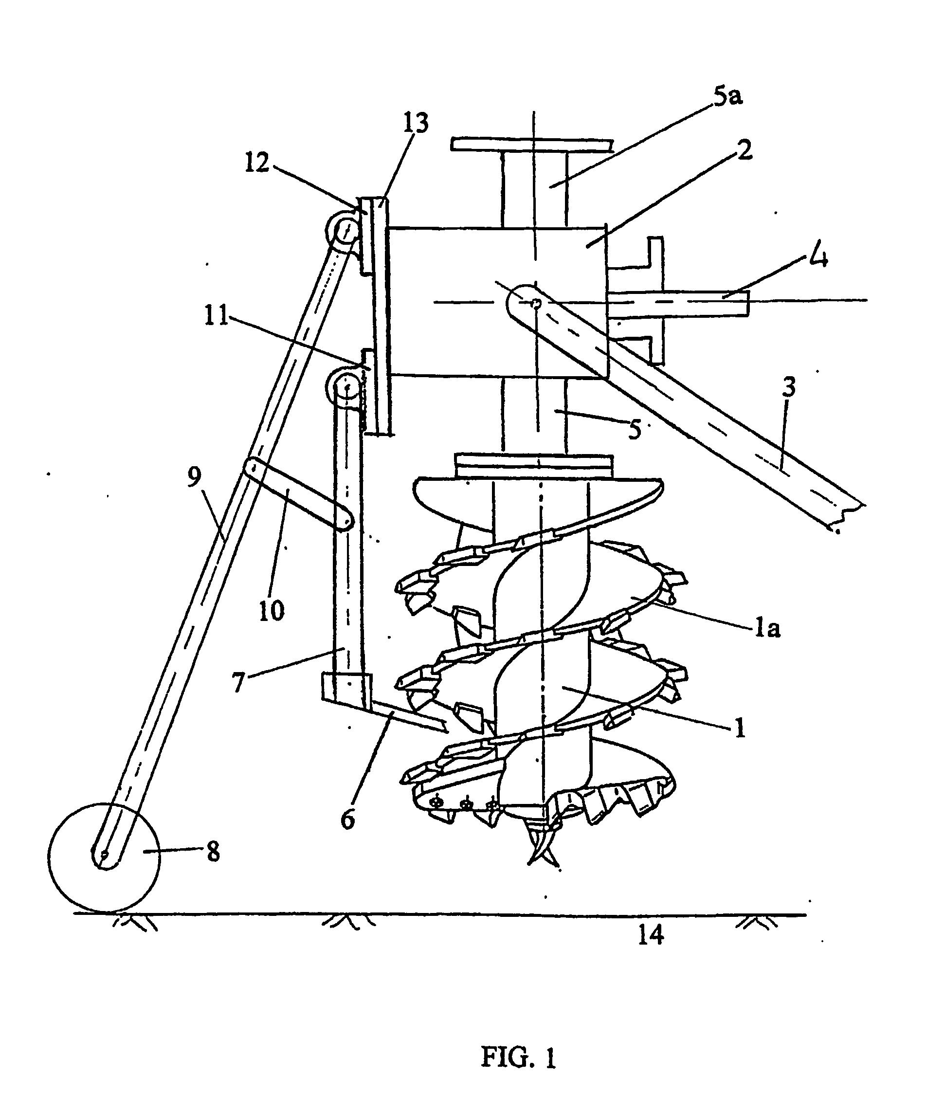
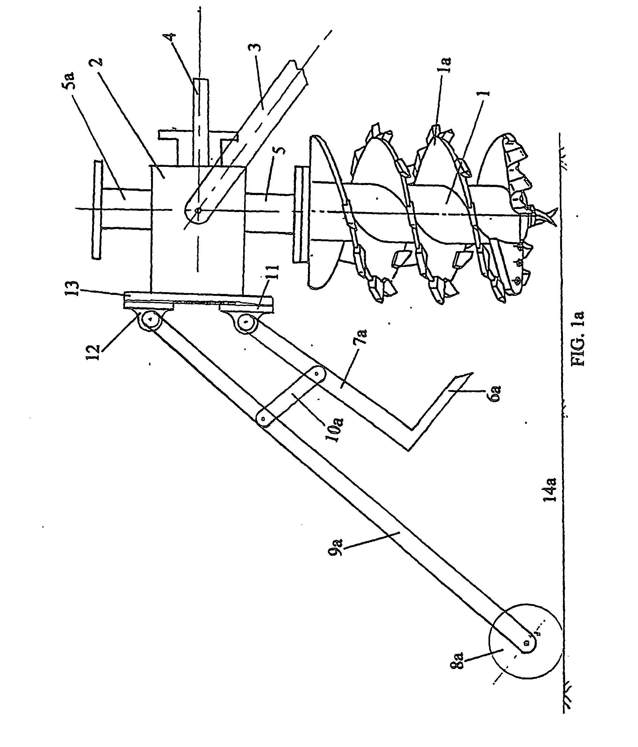
[0031]FIGS. 1, 1a, 1b are a side view of a post hole digger with an automatic stationary-cleaning blades in three positions of operation. The auger digger 1 is in three relative positions to the soil surface: in position 14 the digger is lifted by the lifting arm 3 connected to the operating vehicle, above the soil surface. The stationary-cleaning blade 6 is at its cleaning position, cleaning mud and roots and other debris from the rotating auger digger 1 while the operating vehicle moves to the next digging spot. In position 14a the auger digger is lowered by the arm 3 to touch the soil surface and the depth control wheel 8 moves backward to position 8a. By moving backward the wheel's arm 9 moves with the wheel 8a to the new position 9a. The wheel's arm 9 is connected to the stationary-cleaning blade's arm 7 by a connecting link 10. By moving to position 9a, the wheel's arm pulls the blade's arm 7, via the link 10a to its new position 7a thus pulling the stationary blade 6 outside ...


PUM


Abstract

A travelling rolling digger (1) for sequential hole drilling or for producing sequential cultivated spots in soil. The travelling rolling digger (1) includes at least one drilling shaft which is rotatable by a drive mechanism about a longitudinal shaft axis and has a rotating soil penetrating edge. The drilling shaft is mounted to roll about a horizontal shaft in a soil penetrating plane while the horizontal shaft moves in a direction of travel of the traveling rolling digger. The rotating drilling shaft enters the soil at an entry angle and digs into the soil while the horizontal shaft moves in the direction of travel and the drilling shaft continuously changes its angle relative to the soil from the entry angle to a vertical position. The traveling rolling digger further comprising at least one cleaning blade (6).

Description

BACKGROUND OF THE INVENTION [0001] The present invention relates to a method and devices for cleaning hole diggers and spot cultivators from accumulated mud, which interfere with the digging or cultivating process. It is specially related to rolling hole diggers and spot cultivators as their high rate of digging or cultivating holes is very fast. As the time between holes is very short, it is important to prevent the accumulation of mud mechanically and not cleaning by time consuming and hard manual cleaning. The accumulated mud around hole digging and spot cultivating blades and shafts includes weeds, roots and other debris. The combination of mud with the string-like debris makes it very hard to clean, unless it is being cleaned immediately after digging each hole. The present invention thus provides a simple procedure and devices for cleaning hole diggers and spot cultivators automatically while they are being moved from one hole to the new one. [0002] It is an object of the inve...

Claims


Application Information

Patent Timeline
Patent Type & Authority Applications(United States)
IPC IPC(8): A01B33/06A01B71/08E21B7/02E21B10/44E21B12/06
CPCA01B33/06E21B12/06E21B7/02A01B71/08
Inventor MANOR, GEDALYAHU
Owner MANOR GEDALYAHU
Why Eureka
Try Eureka