Gear mechanism and a rotary encoder equipped with this gear mechanism

a gear mechanism and gear technology, applied in the direction of transmission systems, dynamo-electric machines, toothed gearings, etc., can solve the problems of limiting the installation space required in the axial direction, and the mechanical components of these devices often become limiting factors in such miniaturization efforts, and achieve the effect of small structural dimensions and low cos

Inactive Publication Date: 2005-07-28
DR JOHANNES HEIDENHAIN GMBH
View PDF10 Cites 16 Cited by
  • Summary
  • Abstract
  • Description
  • Claims
  • Application Information

AI Technical Summary

Benefits of technology

[0007] An example embodiment of the present invention may provide a gear

Problems solved by technology

This design may be disadvantageous insofar as it requires relatively large installation space, in particular as far as the outer dimensions in the radial direction are concerned.
Since the electronic components of rotary encoders are integrated to an ever greater exte

Method used


Image

  • Gear mechanism and a rotary encoder equipped with this gear mechanism
  • Gear mechanism and a rotary encoder equipped with this gear mechanism
  • Gear mechanism and a rotary encoder equipped with this gear mechanism

Examples


Embodiment Construction

[0037] Equally acting components of different exemplary embodiments are provided with identical reference signs in the Figures.

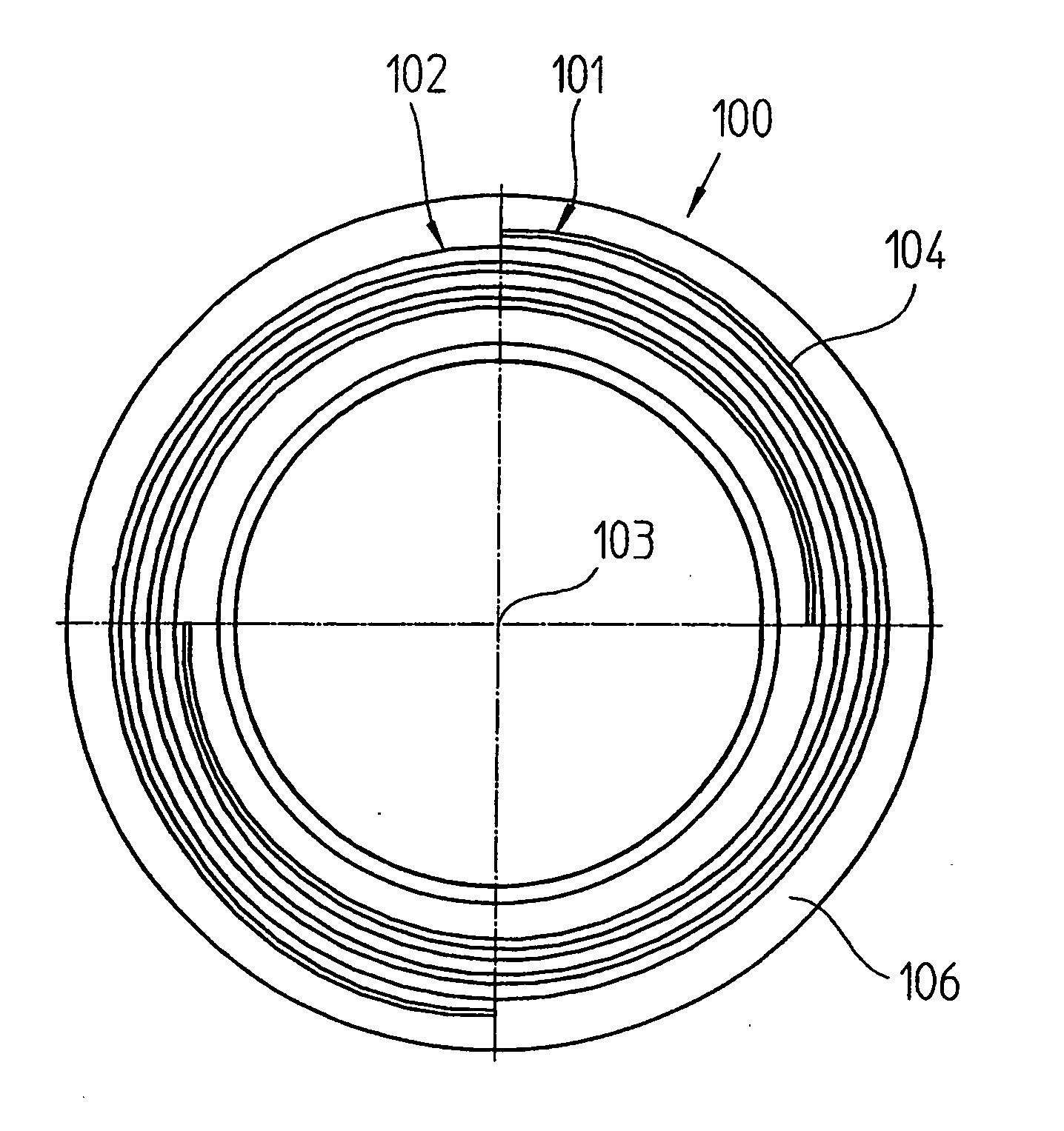
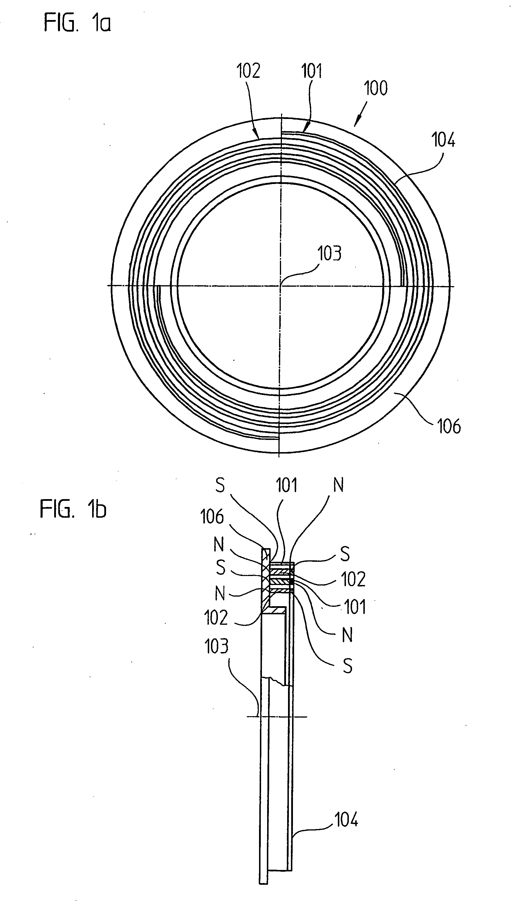
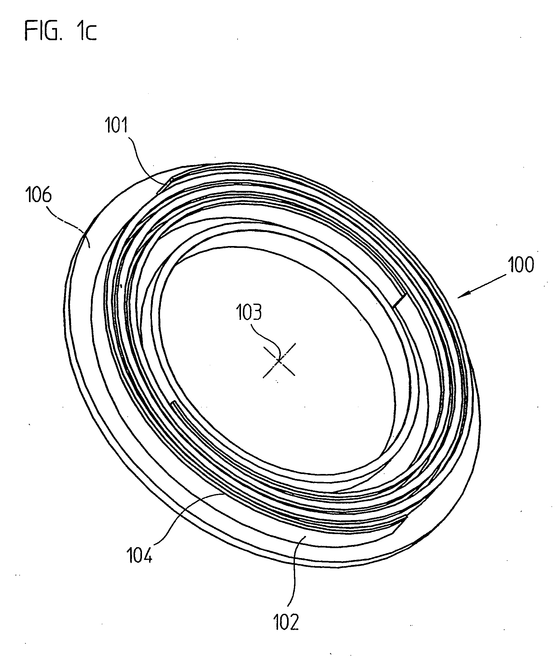
[0038]FIG. 1a is a plan view of drive gear 100 of the gearing according to an example embodiment of the present invention as it is installed as first gear step in a rotary encoder 400 (FIG. 7). Drive gear 100 has a large central bore to accommodate a hollow shaft 401 (shown in FIG. 7), the rotational position of which is measured during operation of rotary encoder 400. At a front end of drive gear 100, aligned along a spiral curve in each case, are two longitudinal permanent magnets 101, 102 (FIG. 1b), which are arranged at a 180° offset, arranged on top is a spiral-shaped plate 104, the edges of which extend according to the form of permanent magnets 101, 102. Plate 104 is bonded to permanent magnets 101, 102. Plate 104 is made of a ferromagnetic alloy, so that the magnetic field of permanent magnets 101, 102 is intensified. Body 106 of drive gear 100 is m...


PUM


Abstract

A gear mechanism includes a rotating input element, a rotating output element, and at least one first force transmission device arranged along a spiral line on a face of the input element. A second force transmission device is arranged along an encircling line on a face of the output element. The interaction of these force transmission devices transmits a turning moment from the input element to the output element, whereby this turning moment effects a rotating motion in the output element so that the rotational speed is lower than the rotational speed of the input element. A rotary encoder may be equipped with a gear mechanism of the aforementioned type.

Description

FIELD OF THE INVENTION [0001] The present invention relates to a gearing and to a rotary encoder equipped with such gearing. BACKGROUND INFORMATION [0002] In addition to angle-measuring instruments, which allow an angle measurement at a rotatable shaft in incrementable measuring steps, so-called absolute angle-measuring instruments—also referred to as rotary encoders—are conventional as well. These allow an absolute angle determination within a single shaft rotation. Furthermore, if the number of performed shaft rotations is to be recorded as well, so-called multiturn rotary encoders are generally utilized. With such multiturn rotary encoders, the absolute angular position is determined within one shaft rotation, i.e., between 0° and 360°, via a code disk connected to the shaft, which is scanned with the aid of a suitable photoelectric scanning unit. To obtain the required information regarding the number of effected shaft rotations, a reduction or step-down gear is typically provid...

Claims


Application Information

Patent Timeline
IPC IPC(8): F16H1/12G01D5/245F16H1/24F16H35/00F16H49/00G01D5/14H02K49/10
CPCF16H1/125F16H1/24Y10T74/19698G01D5/145H02K49/102F16H49/005G01D5/34784G01D11/00G01D2205/26
Inventor BRANDL, ALOISMITTERREITER, JOHANNSCHWABE, MICHAEL
Owner DR JOHANNES HEIDENHAIN GMBH
Why Eureka
Try Eureka