Flexible scan field

a scanning field and flexible technology, applied in the field of energy beam scanning, can solve the problems of performance degradation, complexity and cost of focus lens, and performance degradation

Active Publication Date: 2005-07-28
ELECTRO SCI IND INC
View PDF35 Cites 31 Cited by
  • Summary
  • Abstract
  • Description
  • Claims
  • Application Information

AI Technical Summary

Benefits of technology

[0015] One embodiment of the present invention provides a flexibly optimized material processing system. The system includes a laser emitter configured to emit a laser beam. Beam adjusting optics having a beam expansion ratio are configured to adjust the emitted laser beam by adjusting the beam expansion ratio. Beam directing optics are configured to provide a variable effective pupil corresponding to the adjusted laser beam. The beam directing optics are further configured to direct the adjusted beam to one or more targets within a scan field. A lens, having a field of view encompassing at least the scan field, is configured to focus the directed laser beam onto the one or more targets within the scan field. A control processor is configured to receive input corresponding to a material processing parameter, and to issue at least one optimized control signal based on the at least one material processing parameter. The beam adjusting optics can be, for example, a zoom telescope. The beam directing optics can be, for example, one or more galvanometer mirror scanners. The system may further include a motion system that is configured to move a work piece containing at least one target relative to the scan field, and to position the at least one target within the scan field for processing (e.g., laser trimming of a circuit component or link blasting in a memory array).

Problems solved by technology

Relevant focus lens characteristics include the lens focal length, the lens performance degradation at large angles, the telecentricity of the focus lens, and the complexity and cost of the focus lens.
With regard to degradation, it will be understood that focusing a beam through the outside area of the focus lens will often result in degraded performance when smaller spots are desired.
In addition, beam positional accuracy may be degraded near the perimeter of the focal surface when the field size is increased.
Without increasing the beam pupil size, this will result in the beam having a large spot size at the focal surface.
However, if the pupil size is increased, the size of the mirrors or other beam directing components must also be increased, thereby degrading dynamic performance.
However, if the packing density of the features to be machined is high, resulting in the need for a small beam spot size at the focal surface, then the complexity and cost of designing and manufacturing such a focus lens can be quite high.
This results in increased manufacturing costs.

Method used


Image

  • Flexible scan field
  • Flexible scan field
  • Flexible scan field

Examples


Embodiment Construction

[0033] Embodiments of the present invention can be employed to machine features at various sizes and / or packing densities on work pieces having different sizes and / or shapes. This machining can be accomplished without using different systems and without manually installing and de-installing different focus lenses in the scan subassembly. Various material processing parameters including, for example, field size, accuracy, telecentricity, step size and / or spot size can be flexibly optimized for a particular application.

[0034] Overview

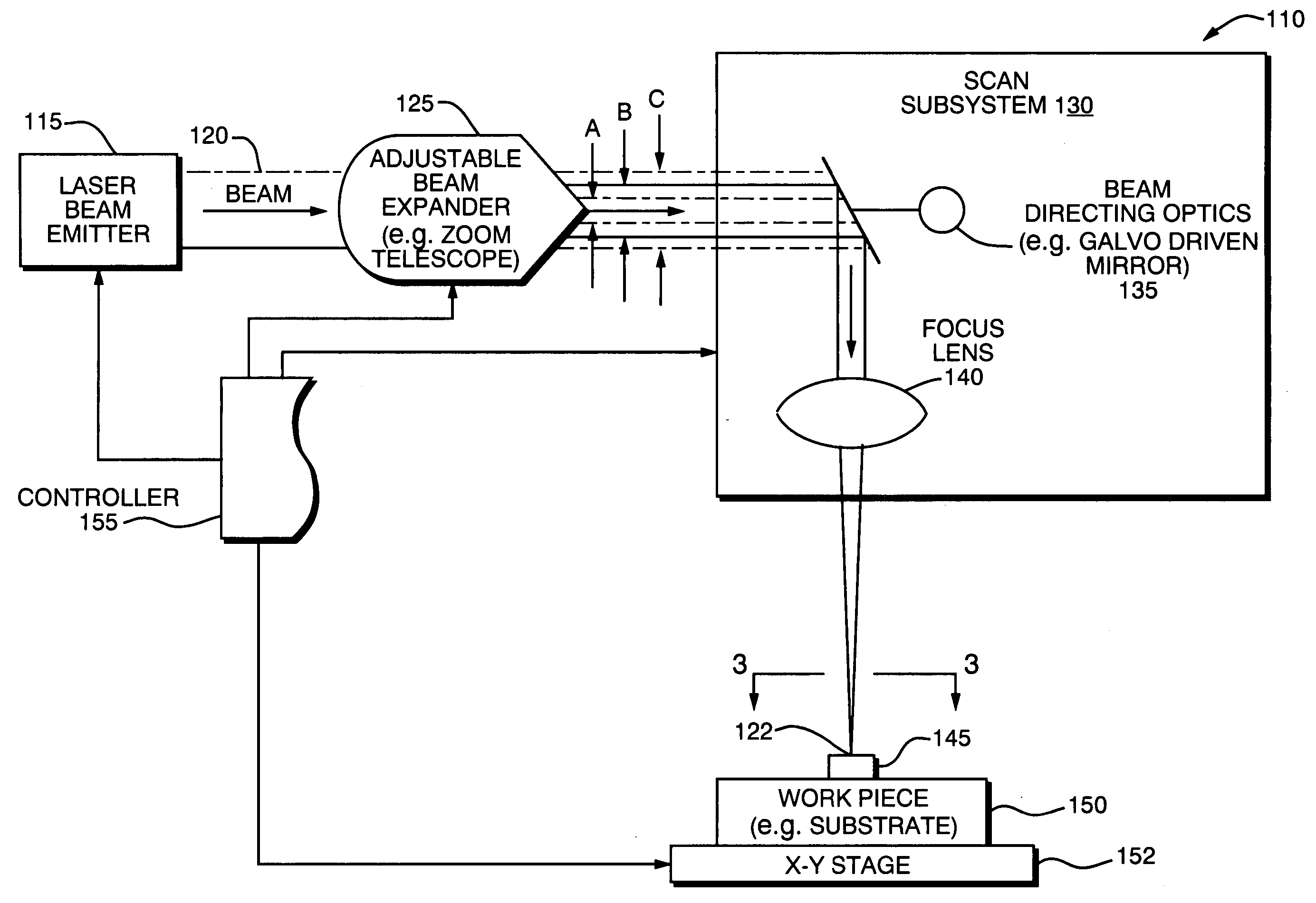
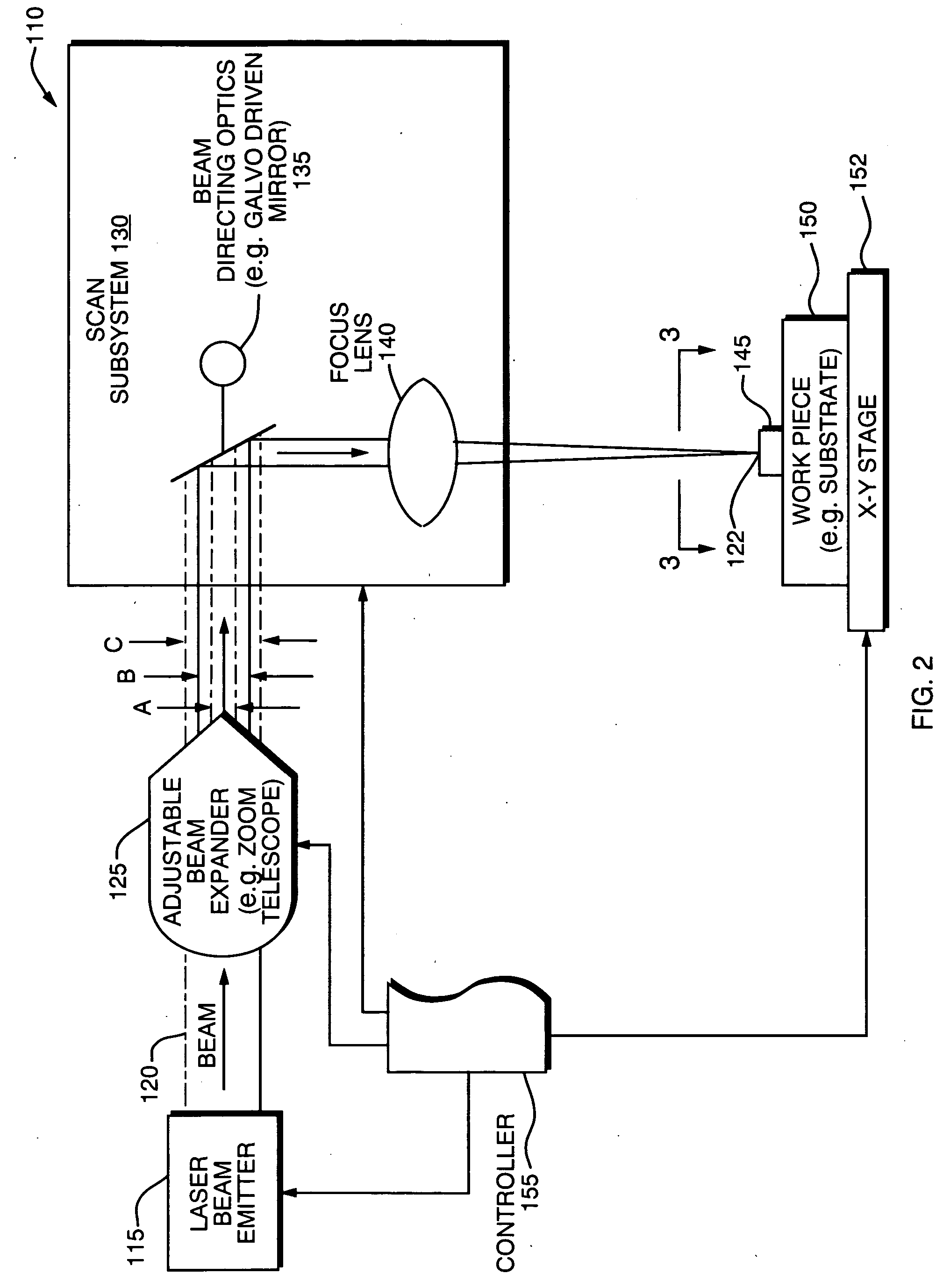
[0035]FIG. 2 depicts a micro-machining system 110 configured in accordance with one embodiment of the present invention. The system could be used for various types of machining operations, such as a trimming operation for untrimmed circuit elements (e.g., film resistors, capacitors, and inductors) formed on a PCB panel or on any panel or other type of substrate. Note that the system 110 can be employed for other applications (e.g., drilling, marking, mi...


PUM

PropertyMeasurementUnit
wavelengthaaaaaaaaaa
laser wavelengthaaaaaaaaaa

Abstract

An energy beam machining system includes an emitter for emitting an energy beam and beam adjusting optics, such as a zoom telescope, for adjusting the pupil size of the system to multiple values. The adjusting of the pupil size can be carried out automatically, semi-automatically, or manually. In manual modes, instructions can be presented to the operator (e.g., via a monitor or pre-programmed audio instruction) indicating how to adjust pupil size. A focus lens focuses the adjusted beam directed along each path at a different focal point within a scan field encompassed in the field of view of the focus lens. Beam directing optics are configured to enable multiple scan fields within the field of view of the focus lens.

Description

RELATED APPLICATIONS [0001] This application claims the benefit of U.S. Provisional Application No. 60 / 512,043, filed Oct. 17, 2003, which is herein incorporated in its entirety by reference.FIELD OF THE INVENTION [0002] The invention relates to energy beam scanning, and more particularly, to optimizing characteristics of a laser beam to the applicable machining operations. BACKGROUND OF THE INVENTION [0003] Energy beams, such as laser beams, are commonly used in numerous different types of machining operations, including what are often referred to as micro-machining operations. In conventional micro-machining operations, laser beams are used to machine features on substrates, such as printed circuit boards and panels. One typical micro-machining operation involves the laser trimming of resistors and capacitors printed on a substrate. [0004]FIG. 1 depicts a conventional laser beam micro-machining system 10 of the type used for resistor trimming. The system 10 includes a laser beam e...

Claims


Application Information

Patent Timeline
Patent Type & Authority Applications(United States)
IPC IPC(8): B23KB23K26/00B23K26/06B23K26/08H01C17/242H01G13/00
CPCB23K26/00B23K26/0003B23K26/0639H01G13/00B23K26/0665B23K26/0807H01C17/242B23K26/0648B23K26/064B23K26/082B23K26/351
Inventor KITAI, ANTON T.EHRMANN, JONATHAN S.
Owner ELECTRO SCI IND INC
Why Eureka
Try Eureka