
Compact multi-level output gas generator

a multi-level output, gas generator technology, applied in the direction of pedestrian/occupant safety arrangement, vehicular safety arrangment, vehicle components, etc., can solve the problems of large, heavy and expensive designs, increase cost, weight and complexity in manufacturing, and increase the cost, complexity and complexity of manufacturing, so as to minimize the cost and size of the assembly, the effect of simple construction

Active Publication Date: 2005-07-28
ARC TECH HLDG LTD
View PDF31 Cites 32 Cited by
  • Summary
  • Abstract
  • Description
  • Claims
  • Application Information

AI Technical Summary

Benefits of technology

[0012] It is an object of the present invention, therefore, to overcome the disadvantages of the prior art and to provide a cost-effective, lightweight, compact and simple multi-level output hybrid inflator or gas generator which is reliable in operation.
[0015] A still further object of the present invention is to provide such a multi-level output inflator or gas generator which may be easily converted to a single level inflator or gas generator in a cost effective manner.
[0016] Another object of the present invention is to provide such a multi-level output inflator or gas generator with one or more simple and effective, separate non-hermetic dividers or divider walls in the center portion thereof that separate the primary and secondary gas generators.
[0018] A further object of the present invention is to provide such a multi-level inflator or gas generator with a standpipe connected to the diffuser in the center portion thereof that, in one embodiment, protrudes outwardly in one direction with radial or lateral flow orifices for improved gas distribution and serving to direct flow away from the occupant.
[0020] Still another object of the present invention is to provide such a multi-level output inflator or gas generator which is simple in construction and easy to assemble to minimize the cost and size of the assembly.
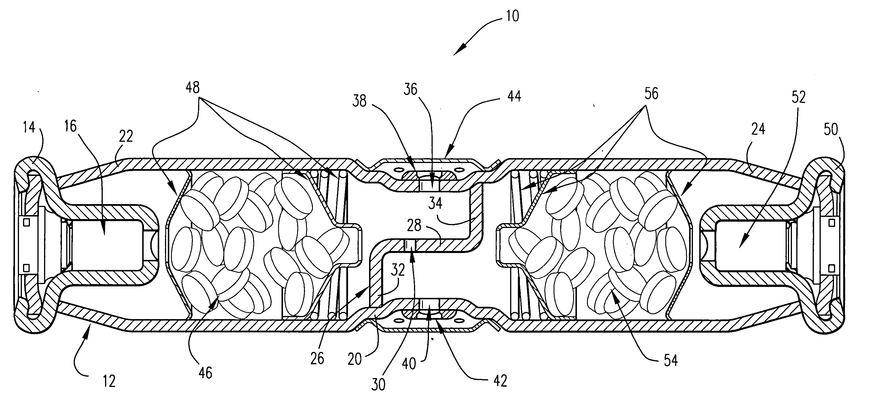
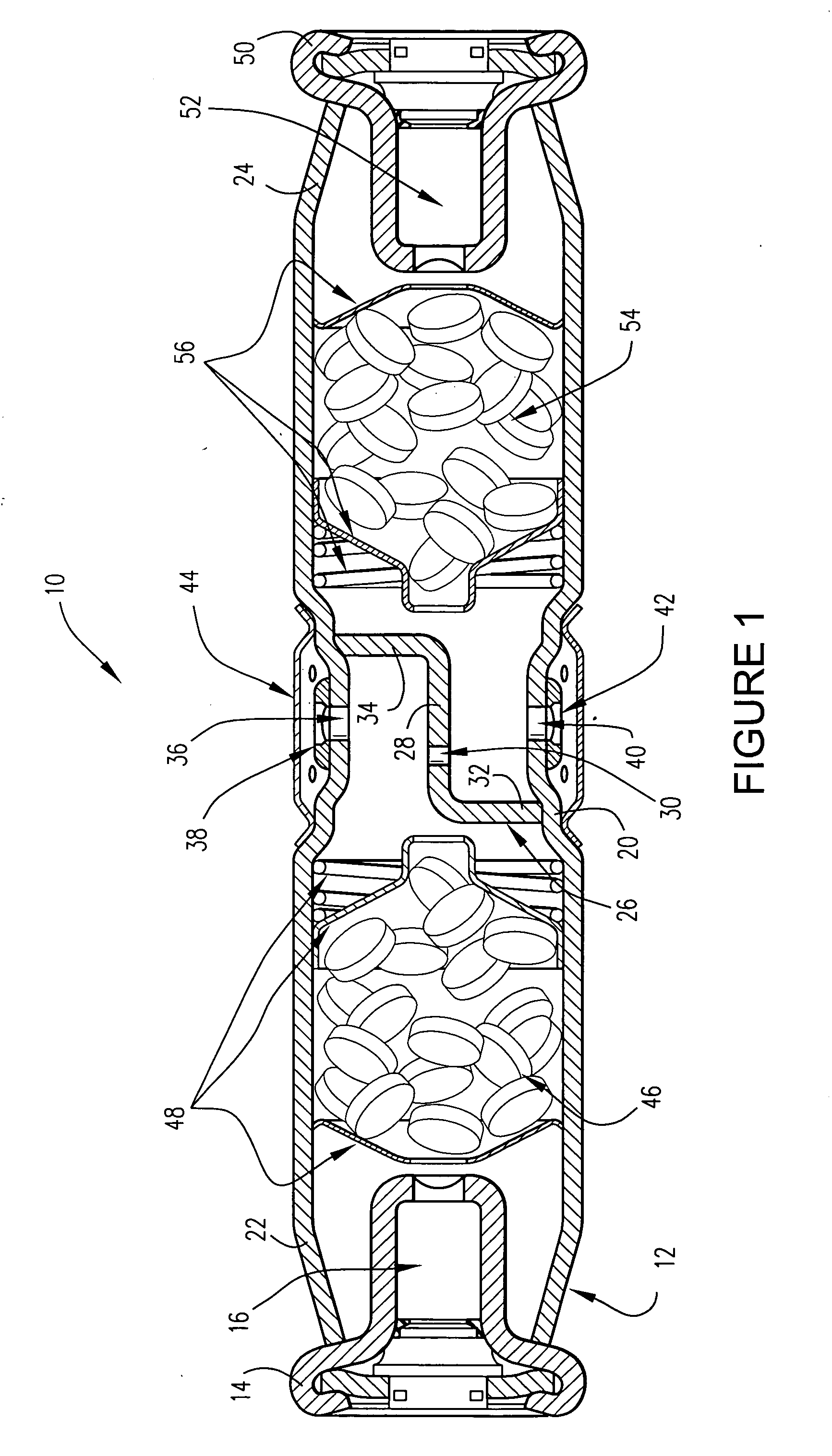
[0021] These and other objects of the present invention are achieved by providing a multi-level output inflator or gas generator for inflating a vehicle safety restraint such as an air bag, comprising a common pressure vessel for a primary gas generator and a secondary gas generator that are separated from each other by one or more simple non-hermetic dividers or divider walls in the center portion thereof. In one embodiment, the divider or divider wall is a separate member. In another embodiment, the dividers are provided by adjacent end walls of the gas generant canisters or cups located in the center portion of the inflator. The gases from the primary and secondary gas generators are directed to a common diffuser in the center portion thereof for inflation of the air bag. The combination of a primary hybrid gas generator and a secondary hybrid gas generator in a simple common pressure vessel in a single multi-level output inflator minimizes size and cost. Also, simple assembly methods, such as magnetic forming, swaging, crimping and welding may be used to assemble the present multi-level output inflator or gas generator because of its simple construction.

Problems solved by technology

Utilizing two separate inflators of the hybrid type, for example, results in large, heavy and expensive designs since nearly every component is duplicated.
Additionally, there is the added requirement of securing the two inflators to a common platform, which in turn increases cost, weight, and complexity in manufacturing.
This arrangement suffers from the drawback of being relatively complex and therefore, relatively expensive.
However, this arrangement is even more complex than that in U.S. Pat. No. 3,773,353.

Method used


Image

  • Compact multi-level output gas generator
  • Compact multi-level output gas generator
  • Compact multi-level output gas generator

Examples


first embodiment

[0037]FIG. 1 illustrates the multi-level output inflator or gas generator 10 of the present invention. The inflator 10 comprises an elongated pressure vessel 12 formed of any suitable material, such as steel, aluminum or the like. An igniter body 14 formed of any suitable material, such as steel, aluminum or the like, and supporting a primary ignition device 16 of any suitable construction is secured to a first end of the pressure vessel 12 in any suitable manner, such as by crimping or a friction weld. The primary ignition device 16, e.g., may be an initiator or a microgas generator.

[0038] The pressure vessel 12 may be formed with an indented portion 20 of any suitable configuration near the middle thereof. The middle or indented portion 20 serves to define a primary gas generant portion 22 of the pressure vessel between the middle or indented portion and the primary ignition device 16, and a secondary gas generant portion 24 between the middle or indented portion and the second or...

second embodiment

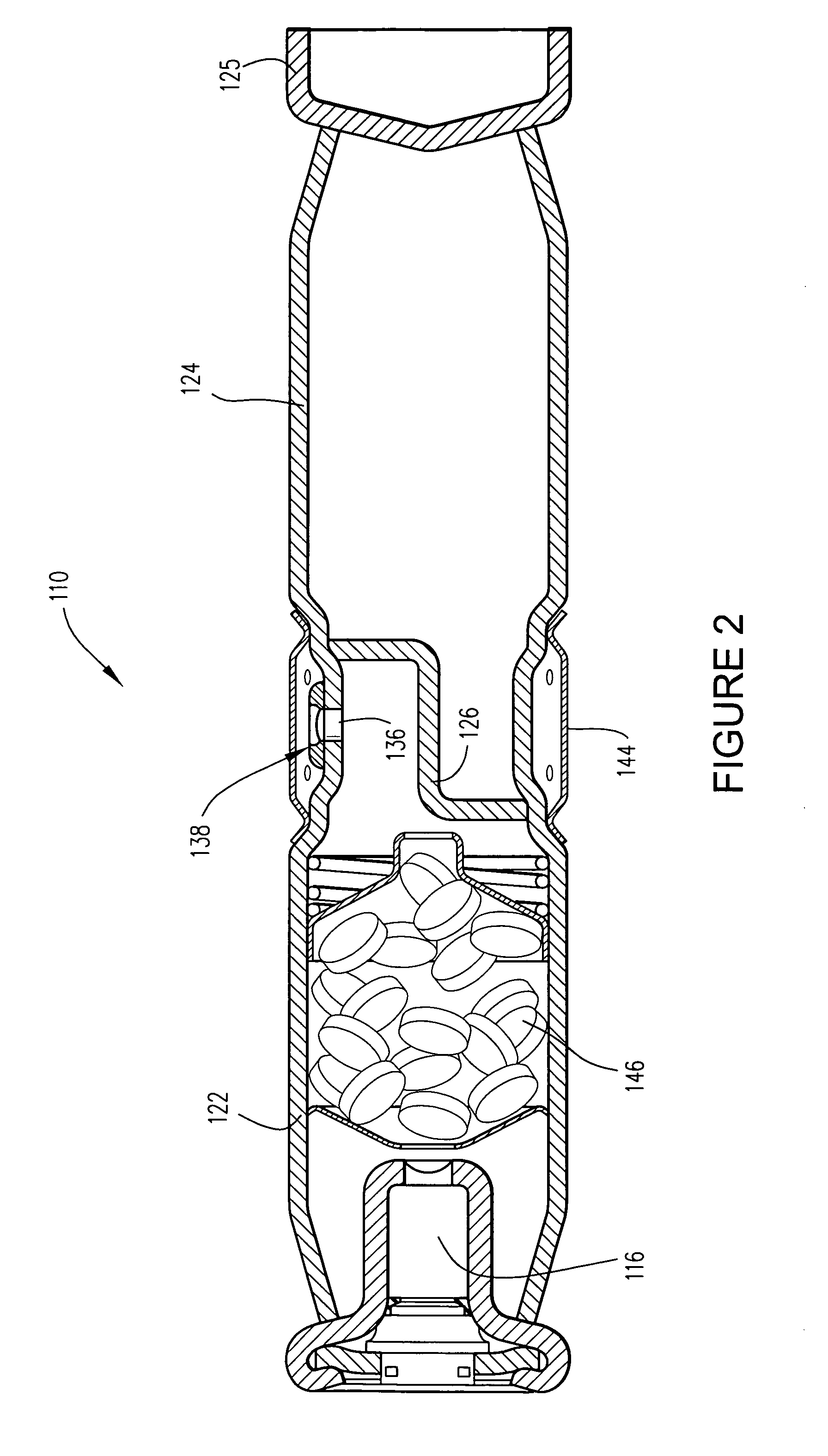
[0048]FIG. 2 is directed to the inflator of the present invention which illustrates the simple manner in which the multi-level inflator of FIG. 1 can be converted into a single level inflator 110 wherein there are no energetics in the secondary portion 124 of the pressure vessel 112. The end of the secondary portion 124 is closed by a closure member 125 of any suitable construction that is secured thereto in any suitable manner. The primary gas generant portion 122 of the pressure vessel 112 includes a primary ignition device 116, primary energetics 146, a primary exit orifice 136, a primary rupture disk 138, a diffuser 144 and a divider 126 which are constructed and operate in substantially the same manner as those shown in FIG. 1. In an alternate construction, when a communication port is provided in the divider 126, a secondary exit orifice and rupture disk like those shown in FIG. 1 may be provided in the secondary portion 124.

[0049]FIG. 3 illustrates a multi-level output inflat...

third embodiment

[0051]FIG. 5 illustrates the multi-level output inflator 410 of the present invention. The inflator 410 comprises an elongated pressure vessel 412 formed of any suitable material. An igniter body 414 formed of any suitable material and supporting a primary ignition device 416 of any suitable construction is secured to a first end of the pressure vessel 412 in any suitable manner such as by crimping. The primary ignition device 416 may be an initiator or a microgas generator.

[0052] The pressure vessel 412 may be formed with an indented portion 420 of any suitable configuration near the middle thereof. The middle or indented portion 420 serves to define a primary gas generant portion 422 of the pressure vessel between the indented portion 420 and the primary ignition device 416, and a secondary gas generant portion 424 between the indented portion 420 and the second or opposite end of the pressure vessel 412.

[0053] A primary gas generant canister 425 formed of any suitable material s...


PUM


Abstract

A multi-level gas inflator for an air bag or other safety device, comprising an elongated pressure vessel having a primary gas generant portion with a first open end and a secondary portion with a second open end. The primary gas generant portion has a primary ignition device and primary gas generating energetics disposed therein. The primary ignition device is mounted on and closes the pressure vessel at the first open end thereof. The secondary portion may have a secondary ignition device and secondary gas generating energetics disposed therein. The secondary ignition device may be mounted on the pressure vessel at the second open end thereof. A suitable gas under a predetermined pressure is present in the primary and secondary portions. One or more separate dividers or divider walls are disposed within the midportion of the pressure vessel to separate the primary and secondary portions. The pressure vessel may have a primary exit orifice in the midportion thereof that is in communication with the primary gas generant portion, and a secondary exit orifice in the midportion thereof that is in communication with the secondary portion. A primary rupture disk is disposed over the primary exit orifice, and a secondary rupture disk is disposed over the secondary exit orifice. A diffuser may be mounted on and surround the pressure vessel midportion and the primary and secondary exit orifices. Each divider or divider wall may have a communication port therethrough.

Description

CROSS REFERENCE TO RELATED APPLICATIONS [0001] The present application is a continuation-in-part of application Ser. No. 10 / 634,797, filed on Aug. 6, 2003.BACKGROUND OF THE INVENTION [0002] 1. Field of the Invention [0003] The present invention relates generally to an inflator or gas generator for an air bag or other safety device and, more specifically, to a compact multi-level output inflator or gas generator which can selectively release gas at different rates and levels and thus enable the air bag or another type of safety device to be deployed or operated at different output levels in accordance with different sensor inputs. [0004] 2. Description of the Related Art [0005] Recently, there has been a demand for controlling the rate and amount of inflation or operation of safety devices such as air bag restraint systems in accordance with variables such as passenger size, position, seat belt usage and the velocity of a vehicle at the time of collision. [0006] In order to provide o...

Claims


Application Information

Patent Timeline
Patent Type & Authority Applications(United States)
IPC IPC(8): B60R21/2338B60R21/261B60R21/263B60R21/268B60R21/272
CPCB60R21/2338B60R21/261B60R21/2644B60R2021/2685B60R2021/23384B60R2021/2633B60R2021/2648B60R21/272B60R21/16B60R21/263
Inventor BILBREY, DAVID ANTHONYCOLBURN, SCOTT JOSEPHHUSBAND, C. RICHARDROVITO, ROBERT WILLIAMHANCOCK, SAMUEL MORGAN
Owner ARC TECH HLDG LTD
Learn More