Overload protection for DC motors

a dc motor and overload protection technology, applied in the direction of motor/generator/converter stopper, dynamo-electric converter control, ac motor stopper, etc., can solve the problems of damage to the motor, damage to the motor or the control mechanism of the motor itself, damage to the motor and/or the control circuitry,

Inactive Publication Date: 2005-07-28
SIEMENS VDO AUTOMOTIVE CORP
View PDF3 Cites 26 Cited by
  • Summary
  • Abstract
  • Description
  • Claims
  • Application Information

AI Technical Summary

Benefits of technology

[0008] An object of the invention is to fulfill the need referred to above, in accordance with the principles of the invention; this object is obtained by providing a closed-loop system for controlling a DC motor. The system includes a DC motor, a controller associated with the motor and constructed and arranged to control operation of the motor, a voltage sensor constructed and arranged to measure a voltage supplied to the motor, speed measurement structure associated with the motor and constructed and arranged to obtain the measured speed of the motor, and a conditioning circuit constructed and arranged to receive a speed signal and condition the speed signal to provide to the controller, a nominal speed based on the voltage supplied to the motor. The controller is constructed and arranged to compare the measured speed with an expected speed, that is less than the nominal speed, at a voltage corresponding to a measured voltage, and if the measured speed is less than the expected speed, a fault condition is defined by the controller.
[0009] In accordance with another aspect of the invention, a method is provided for detecting a fault condition of a closed-loop DC motor system. The system includes a DC motor, a controller associated with the motor and constructed and arranged to control operation of the motor, a voltage sensor constructed and arranged to measure a voltage supplied to the motor, speed measurement structure associated with the motor and constructed and arranged to obtain a measured speed of the motor, and a conditioning circuit constructed and arranged to receive a speed signal and condition the speed signal to provide to the controller, a nominal speed, based on the voltage supplied to the motor. The method obtains the expected, or desired speed of the motor, measures the voltage supplied to the motor at the desired speed, defines a lowest possible desired speed of the motor at the measured voltage, after a speed of the motor has reached a steady-state condition, measuring the steady-state motor speed, and defines a fault condition when the measured steady-state motor speed is less than the lowest possible desired speed.
[0010] In accordance with yet another aspect of the invention, a method of detecting a fault condition of a closed-loop DC motor system is provided. The system includes a DC motor, a controller associated with the motor and constructed and arranged to control operation of the motor, a voltage sensor constructed and arranged to measure a voltage supplied to the motor, speed measuring structure associated with the motor and constructed and arranged to obtain a measured speed of the motor, and a conditioning circuit constructed and arranged to receive a speed signal and condition the speed signal to provide to the controller, a nominal speed, based on the voltage supplied to the motor. The method obtains a desired rate of change of speed of the motor, measures the voltage supplied to the motor at the nominal speed, defines a limit of the desired speed of the motor at the measured voltage, and defines a fault condition when the measured rate of change of speed deviates a certain amount from the limit of the desired rate of change of speed.
[0011] Other objects, features and characteristics of the present invention, as well as the methods of operation and the functions of the related elements of the structure, the combination of parts and economics of manufacture will become more apparent upon consideration of the following detailed description and appended claims with reference to the accompanying drawings, all of which form a part of this specification.

Problems solved by technology

Damage to the motor can be caused by continuing to energize the motor in the event of a locked rotor, or reduced speed conditions that can result from full or partial obstruction of the motor rotor.
Under these conditions, damage to the motor or the control mechanism for the motor itself can be the result.
Due to the characteristics of the temperature / current measuring conditioning circuitry, however, damage may occur to the motor and / or control circuitry due to the potentially long time constants associated with conditioning circuits.
As such, current protection schemes may not protect the motor or control electronics under all foreseeable overload conditions.
In addition, the additional circuitry associated with current / temperature limiting circuitry may increase the overall system cost due to the additional components required, as well as the process steps required to ensure repeatable, reliable operation of these circuits across production lots, and all operational conditions.

Method used


Image

  • Overload protection for DC motors
  • Overload protection for DC motors
  • Overload protection for DC motors

Examples


Embodiment Construction

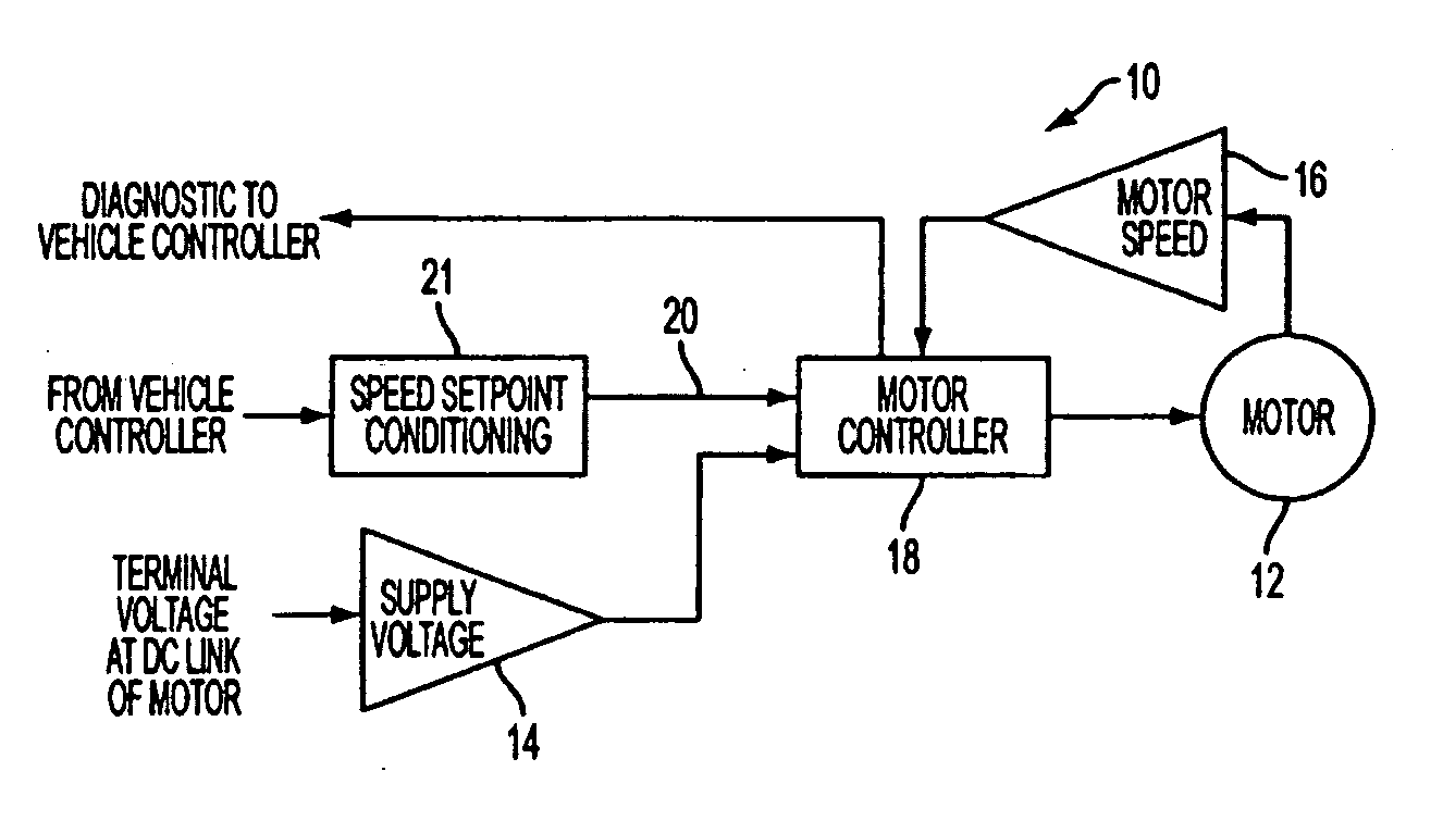
[0020] With reference to FIG. 7, a closed-loop control system for a DC motor is shown schematically, generally indicated at 10, in accordance with the invention. The system 10 includes a DC motor 12, a voltage sensor 14 for determining a supply voltage of the motor, speed measuring structure, for example, a sensor 16, for measuring a speed of the motor 12, a conditioning circuit 21 and control electronics 18. The voltage sensor 14, for example, can include circuitry such as a resistor divider network fed to an analog-to-digital converter or could include a series of discrete values from a comparator chain. The speed sensor 16 can be, for example, circuitry for conditioning the back electro-magnetic force (EMF) induced in the motor windings, a Hall effect sensor, or a reluctance coil.

[0021] The control electronics or controller 18 can include a micro-controller, or analog control device. The speed set-point conditioning circuit 21 is associated with the controller 18 and receives a ...


PUM


Abstract

A closed-loop system 10 is provided for controlling a DC motor. The system includes a DC motor 12, a controller 18 associated with the motor and constructed and arranged to control operation of the motor, a voltage sensor 14 constructed and arranged to measure a voltage supplied to the motor, a speed sensor 16 associated with the motor and constructed and arranged to obtain a measured speed of the motor, and a conditioning circuit 21 constructed and arranged to receive a speed signal and condition the speed signal to provide to the controller, a nominal speed based on the voltage supplied to the motor, or nominal rate of acceleration or deceleration upon a change in the desired speed. The controller 18 is constructed and arranged to compare the measured speed with a certain speed, that is less than the nominal speed, at a voltage corresponding to a measured voltage, and if the measured speed is less than the certain speed, a fault condition is defined by the controller. The controller 18 is also constructed and arranged to compare the measured rate of change of speed with a desired rate of change of speed, that is more than the nominal rate of change of speed in the case of motor acceleration, or less than the nominal rate of change of speed in the case of deceleration, at a voltage corresponding to a measured voltage, and if the measured rate of change of speed differs significantly from the expected rate of change of speed, a fault condition is defined by the controller.

Description

[0001] This application is based on U.S. Provisional Application No. 60 / 538,346 filed on Jan. 22, 2004 and claims the benefit thereof for priority purposes.FIELD OF THE INVENTION [0002] The invention relates to DC motors and, more particularly, to a process of protecting brush or brushless DC motors during overload conditions that may be the result of, but not limited to, seized bearings, snow packing conditions, and load obstructions without the use of current sensing. BACKGROUND OF THE INVENTION [0003] Brush and brushless DC motors have been used frequently in battery-supplied applications, such as automotive, electric vehicle, forklift, etc. Damage to the motor can be caused by continuing to energize the motor in the event of a locked rotor, or reduced speed conditions that can result from full or partial obstruction of the motor rotor. Under these conditions, damage to the motor or the control mechanism for the motor itself can be the result. [0004] In the control of a DC motor,...

Claims


Application Information

Patent Timeline
Patent Type & Authority Applications(United States)
IPC IPC(8): H02P6/06H02P7/00H02P7/28H02P29/02
CPCH02P6/06H02P29/02H02P7/2805
Inventor MAKARAN, JOHN E.
Owner SIEMENS VDO AUTOMOTIVE CORP
Why Eureka
Try Eureka