Class-D amplifier

a class-d amplifier and amplifier technology, applied in the direction of amplifiers, dc amplifiers with modulator-demodulator, amplifiers, etc., can solve the problems of coil and capacitor electrical destruction, impede the improvement of the efficiency of this class-d amplifier,

Inactive Publication Date: 2005-07-28
YAMAHA CORP
View PDF1 Cites 49 Cited by
  • Summary
  • Abstract
  • Description
  • Claims
  • Application Information

AI Technical Summary

Benefits of technology

[0013] The present invention has been made to solve the above-described problems, and therefore, is to provide a class-D amplifier capable of suppressing an output peak when the class-D amplifier is brought into either no load condition or a light load condition.

Problems solved by technology

As a consequence, in the above-described conventional class-D amplifier, the damper circuit is necessarily required, which impedes the improvement in the efficiency of this class-D amplifier.
The conventional power amplifier described in the above-described patent publication 1 owns such a problem that in order to suppress the output peak of the class-D power amplifier, the complex circuit such as the peak voltage detecting circuit and the drive voltage control circuit other than the class-D amplifier is required.
Both a coil and a capacitor which are directly connected to the motor (load) cannot be protected, and thus, there are some possibilities that these coil and capacitor are electrically destroyed.

Method used


Image

  • Class-D amplifier
  • Class-D amplifier
  • Class-D amplifier

Examples


Embodiment Construction

[0045] Referring now to drawings, various embodiment modes of the present invention will be described.

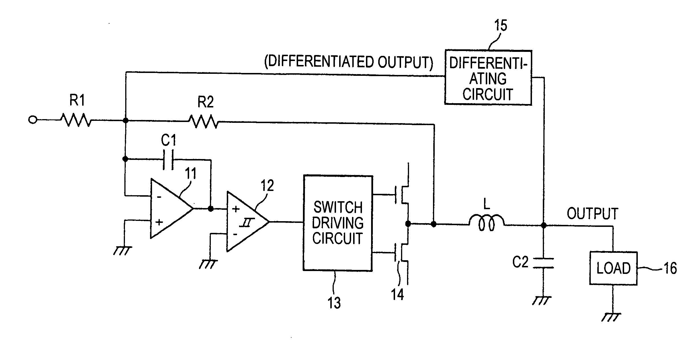
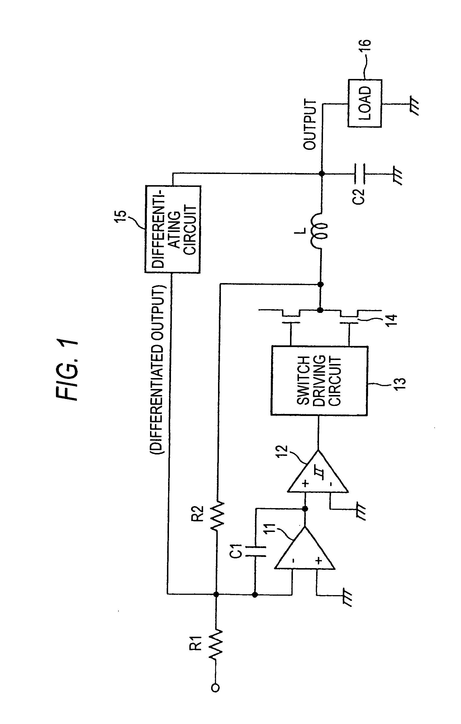
[0046]FIG. 1 is a circuit diagram for indicating a structural example of a class-D amplifier (self-excited type) according to an embodiment mode of the present invention.

[0047] This class-D amplifier is arranged by resistors R1 and R2, capacitors C1 and C2, an operational amplifier 11, a comparator (normally, hysteresis comparator) 12, a switch driving circuit 13, a switch circuit 14, a coil “L”, and a differentiating circuit 15. In this circuit, the resistors R1 and R2, the capacitor C1, the operational amplifier 11, the comparator 12, the switch driving circuit 13, and the switch circuit 14 constitute a pulse width modulating (PWM) circuit.

[0048] Next, a description is made of this pulse width modulating circuit. One end of the resistor R1 constitutes an input terminal of an analog input signal. Both the operational amplifier 11 and the capacitor C1 constitute an integrator. Th...


PUM


Abstract

A class-D amplifier for pulse-width-modulating an analog input signal to output a pulse-width-modulated signal, includes: a differentiating circuit for differentiating the pulse-width-modulated signal of the class-D amplifier; and a negative feedback circuit for feeding back the differentiated signal of the differentiating circuit to an input side of the class-D amplifier in a negative feedback manner.

Description

BACKGROUND OF THE INVENTION [0001] The present invention is related to a class-D amplifier. [0002] Class-D amplifiers perform power amplifications by pulse-width-modulating (PWM) input signals, and are utilized so as to perform power amplifications of audio signals. As related class-D amplifiers, there is such a class-D amplifier which is arranged by a pulse width modulating unit for pulse-width-modulating analog input signals, a low-pass filter positioned at a post stage of the pulse width modulating unit, and a damper circuit positioned at a post stage of the low-pass filter. A speaker, or the like, which constitutes a load is connected parallel to this damper circuit. [0003]FIG. 6 shows an example of a conventional class-D amplifier (self-excited type). A pulse width modulating unit provided in this conventional class-D amplifier is arranged by a resistor R1, an operational amplifier 11, a capacitor C1, a comparator 12, a switch driving circuit 13, a switch circuit 14, and a resi...

Claims


Application Information

Patent Timeline
Patent Type & Authority Applications(United States)
IPC IPC(8): H03F3/217
CPCH03F3/2171
Inventor MAEJIMA, TOSHIO
Owner YAMAHA CORP
Why Eureka
Try Eureka