Surface illumination device and display using the same

a technology of surface illumination and display device, which is applied in the direction of lighting and heating apparatus, instruments, mechanical equipment, etc., can solve the problems of scarification of display qualities, reducing the efficiency of utilizing light emitted from a light source, and the inability of the reflection film to completely prevent such unmodulated light from reflecting, etc., to achieve the effect of reducing the size and weight of the devi

Inactive Publication Date: 2005-07-28
KONINKLIJKE PHILIPS ELECTRONICS NV
View PDF4 Cites 6 Cited by
  • Summary
  • Abstract
  • Description
  • Claims
  • Application Information

AI Technical Summary

Benefits of technology

[0026] This makes it possible to perform un-divergence without the increase of the number of parts as in the past, which is advantageous in manufacturing respects and can contribute to reduction of size and weight of the device.
[0027] In this aspect, the light guide body section may have a light exit face faced toward an end face of the light guide p...

Problems solved by technology

However, the anti-reflection film does not completely prevent reflection of such un-modulated light toward the outside of the display face and some part of the light that enters the film is still reflected.
Therefore, display qualities are scarified...

Method used


Image

  • Surface illumination device and display using the same
  • Surface illumination device and display using the same
  • Surface illumination device and display using the same

Examples


Embodiment Construction

)

[0037] These and other aspects of the invention will be described in more detail below with reference to the attached drawings.

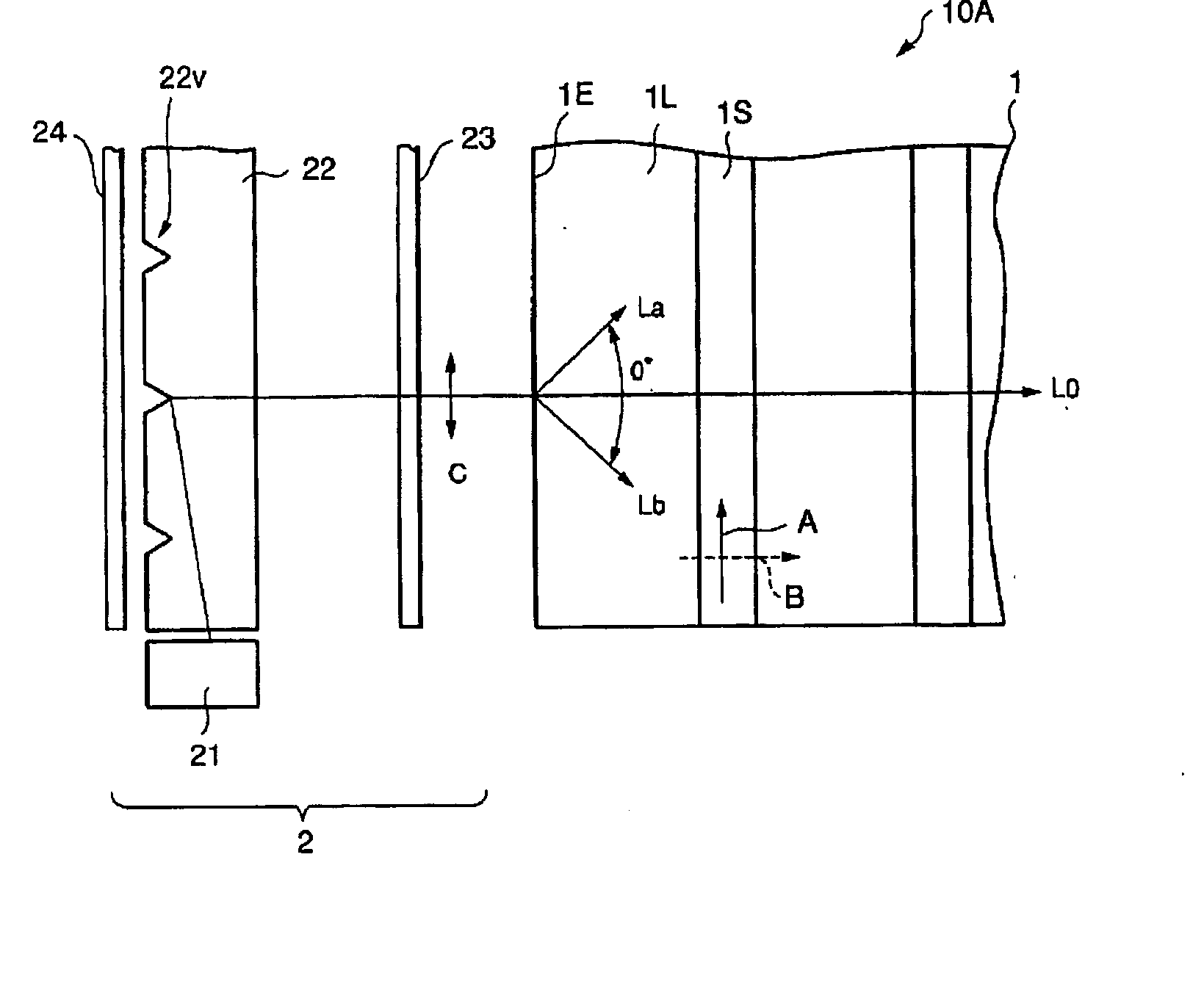
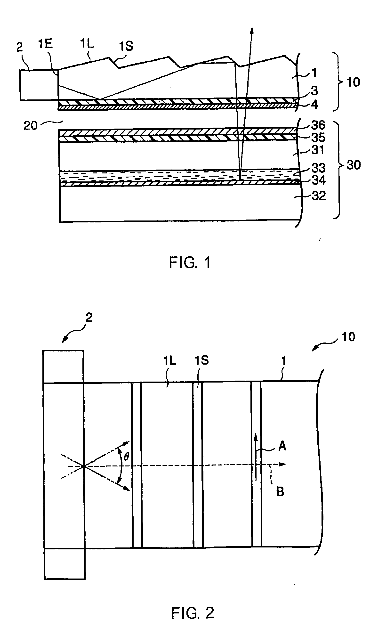
[0038]FIG. 1 schematically shows a sectional structure of a front light according to one embodiment of the present invention and a reflective liquid crystal display device using it, and FIG. 2 is a schematic plan view of this front light.

[0039] In FIG. 1, a front light 10 has a light guide plate 1 and a side light section 2 placed on an end face 1E side of the front light. The front light 10 of this embodiment also includes a polarizing plate 3 directly bonded to the underside of the light guide plate 1 and an anti-reflection film 4 formed on the polarizing plate 3 in such a manner as to cover the polarizing plate 3.

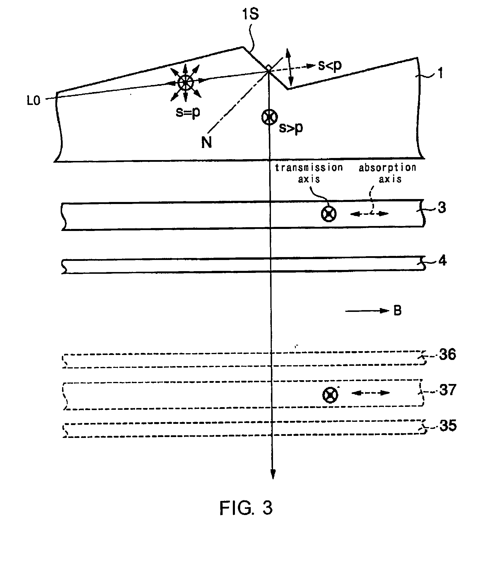
[0040] The light guide plate 1 has a prism surface layer portion with alternating projections and depressions on its upside. This prism surface layer portion is formed, in this example, based on combinations by alternation of a gentle slope 1...


PUM


Abstract

An object of the invention is to provide a surface illumination device and a display device using it, which can contribute to improvement of display qualities. A surface illumination device 10 comprising a light guide plate 1 for propagating incident light inside itself and reflecting the light at the reflecting prism face 1S to output the light from the light exit face. This further comprises: a polarizing plate 3 provided on the light exit face; and an anti-reflection film 4 provided on the polarizing plate 3. The reflecting prism face 1S extends so that a direction of electric vector's vibration of an s-polarized light component of a reflecting light ray caused by an incident light ray in a predetermined propagation direction is in parallel with a polarization axis of the polarizing plate 3, whereby a light efficiency can be improved.

Description

BACKGROUND OF THE INVENTION [0001] 1. Field of the Invention [0002] The present invention relates to a surface illumination device and a display device using it. [0003] The present invention also relates to a surface illumination device and a display device using it, which comprise a light guide plate and means for introducing light to an end face of this light guide plate, wherein light propagating through the light guide plate is directed to an object placed on the undersurface side of the light guide plate so that the whole oncoming face of the object is irradiated with the light as uniformly as possible. [0004] The present invention also relates to a front light system based on such a surface illumination device and a liquid crystal display device with the front light system, and more particularly to a reflective or transflective liquid crystal display device. [0005] 2. Description of the Related Art [0006] A reflective or transflective liquid crystal display device has a liquid...

Claims


Application Information

Patent Timeline
IPC IPC(8): G02B6/00F21V8/00F21Y101/02G02F1/1335G02F1/13357
CPCG02B6/0038G02B6/0055G02F2001/133616G02F1/13362G02B6/0056G02F1/133616G02F1/1335
Inventor TSUDA, AKIMITSUTAKAHASHI, SATORUHUCK, HUBERTINA PETRONELLA MARIANASU, KOUSUKE
Owner KONINKLIJKE PHILIPS ELECTRONICS NV
Why Eureka
Try Eureka