Packet transfer apparatus

a technology of packet transfer and transfer apparatus, which is applied in the field of packet transfer apparatus, can solve the problems of wasting a frequency band, unable to manage multicast destinations, and delay in actual addition or deletion of subscribers, so as to reduce traffic in the access carrier network, use flexibly and effectively

Inactive Publication Date: 2005-07-28
HITACHI LTD
View PDF7 Cites 66 Cited by
  • Summary
  • Abstract
  • Description
  • Claims
  • Application Information

AI Technical Summary

Benefits of technology

[0018] Conventionally, in multicast L2TP communication, the LAC cannot manage multicast destinations when distributing multicast packets. The present invention enables an IGMP or MLD packet sent from a subscriber to be selectively taken out of a PPP connection, so that the LAC can implement a multicast packet distribution function while managing multicast destinations. This causes the multicast destination list to be updated earlier and also causes traffic in the access carrier network to be reduced by the amount of sequence for synchronizing the multicast destination list between the LNS and the LAC, which is described in an IETF draft (draft-ietf-12tpext-mcast-03.txt). A plurality of L2TP sessions configured between one LAC and a plurality of LNSs, if any, are consolidated to a single multicast L2TP session between LAC and LNS. In addition, the load of the line can be distributed over the plurality of L2TP sessions, so that the frequency band of the access carrier network can be used flexibly and effectively. The present invention is applied to the LAC only, and the LNS having the conventional multicast function can be used together with the LAC.

Problems solved by technology

In an access network of the L2TP type, a user IP packet is transferred by a PPP connection, but a general LAC just sends and receives the PPP connection and does not perform processing on the IP packet level.
The LAC cannot manage multicast destinations.
This sequence causes a delay in actual addition or deletion of the subscriber and wastes a frequency band for transferring the destination list.

Method used


Image

  • Packet transfer apparatus
  • Packet transfer apparatus
  • Packet transfer apparatus

Examples


Embodiment Construction

[0047] 1. System Configuration

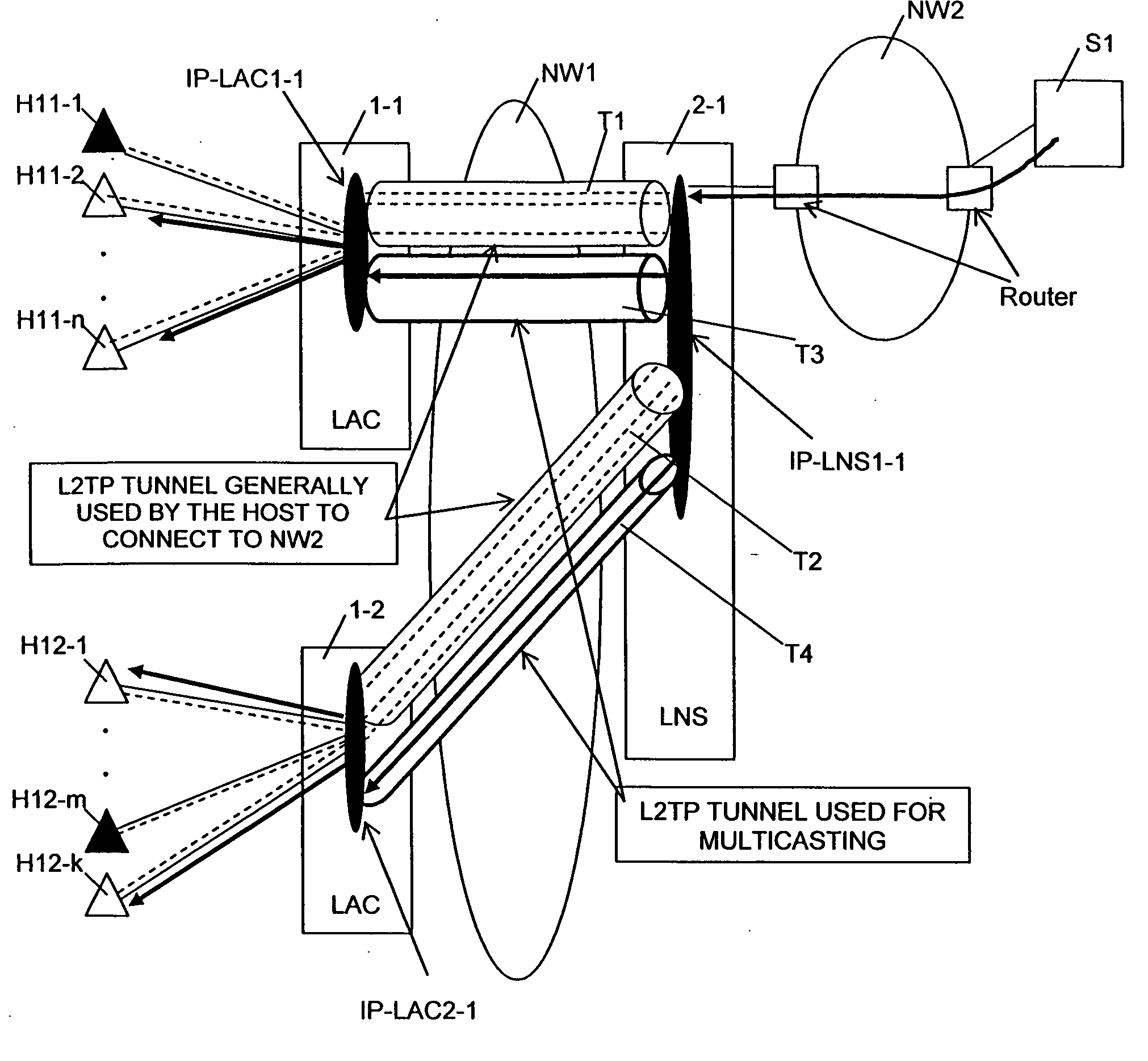
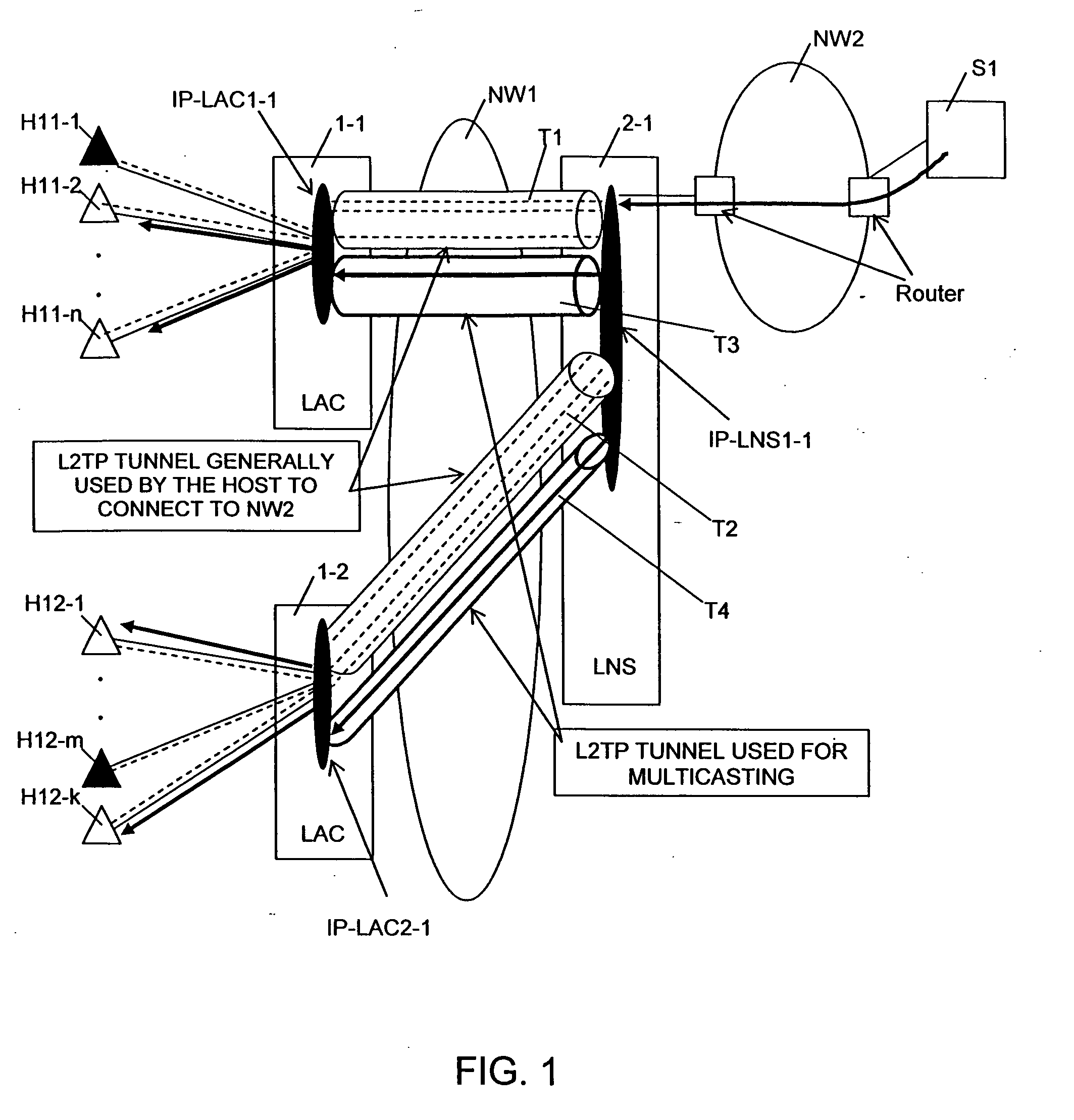
[0048]FIG. 1 shows an example configuration of a network where one embodiment of the present invention is applied. The example network is configured with subscriber terminals H1i-j, LACs 1-i, LNSs 2-i, server S1, access carrier network NW1, and network NW2 such as the Internet (i=1 to n; j=1 to n). The subscriber terminals use PPP and are connected through an ISP to the Internet by IP. An L2TP logical path is formed in access carrier network NW1 between a subscriber and an LNS of the ISP. An L2TP tunnel and an L2TP session are formed between LAC 1-i and LNS 2-i, and LNS 2-i is connected to server S1 through network NW2 with routers. Data is transferred between each subscriber and the Internet through the L2TP connection. When server S1 on network NW2 distributes the multicast packets of a program or the like to the subscribers, the packet transfer apparatus according to this embodiment can make and distribute a copy of the packet to each subscriber whi...


PUM


Abstract

An LAC manages multicast destinations, and forms and distributes copies of the multicast packets. An L2TP tunnel and an L2TP session are formed between LAC 1-i and LNS 2-i, and LNS 2-i is connected to network NW2 such as the Internet. Data is transferred between a subscriber and the network through the L2TP connection. LNS 2-i and sever S1 are connected through network NW2 which has routers. A packet transfer apparatus enables LAC 1-i to manage subscriber information and to form and distribute copies of the packets to the subscribers when server S1 on network NW2 distributes multicast packets of a program or the like to the subscribers.

Description

BACKGROUND OF THE INVENTION [0001] 1. Field of the Invention [0002] The present invention relates to packet transfer apparatuses, and more specifically, to a packet transfer apparatus which terminates Layer 2 Tunneling Protocol (L2TP) on a subscriber side. [0003] 2. Description of the Related Art [0004] One known system uses Point-to-Point Protocol (PPP) to authenticate a subscriber as a user when a subscriber terminal is connected via an Internet service provider (ISP) to the Internet. PPP is a protocol for making a one-to-one connection between a subscriber terminal and an ISP, at a level equivalent to layer 2. PPP was originally used in an environment where a terminal is connected directly to an ISP access point by phone line, authenticated, and then connected to the Internet. As continuous access to the Internet has become common, the connection between the subscriber terminal and the ISP server is currently made through an access carrier network utilizing Internet Protocol (IP)...

Claims


Application Information

Patent Timeline
Patent Type & Authority Applications(United States)
IPC IPC(8): H04L12/46H04L12/66H04L45/16
CPCH04L12/4633
Inventor OTA, MIGAKUMIYATA, HIROAKINAKAJIMA, JUN
Owner HITACHI LTD
Why Eureka
Try Eureka