Production method for optical lens and production method for optical fiber connector

a production method and technology for optical fibers, applied in the field of optical lens production methods, can solve the problems of reducing quality and reliability, difficult alignment of difficulty in aligning the optical axis of the optical fiber wire inserted in the connector body b>, so as to reduce the influence of volume shrinkage, improve the light collection characteristic of the optical lens, and facilitate fine adjustment

Inactive Publication Date: 2005-07-28
JAPAN SCI & TECH CORP +2
View PDF3 Cites 2 Cited by
  • Summary
  • Abstract
  • Description
  • Claims
  • Application Information

AI Technical Summary

Benefits of technology

[0013] The present inventors diligently studied a production method for an optical lens, by which a lens surface shape is easily fine adjusted and a light collection characteristic of the optical lens is improved. As a result, the present inv

Problems solved by technology

However, in the case where the aspherical lens 8 having a minute diameter of about 1 mm is fitted into the connector body 2, it is very difficult to align an optical axis of the optical fiber wire inserted in the connector body 2 and an optical axis of the aspherical lens 8.
There is such a problem that misalignment of optical axes decreases quality and reliability and increases a cost of products.
Therefore, the problem here is that its production steps become complicated.
However, according to the production method for the lens disclosed in the Japanese Unexamined Patent Application Publication No. 23015/2002, when the resin is hardened by the irradiation of the ultraviolet rays while the wave front measurement is performed, volume shrinkage (polymerization shrinkage) of the resin occurs greatly, so that a lens length (i.e. height of the ultraviolet hardening resin) becomes short after the resin

Method used


Image

  • Production method for optical lens and production method for optical fiber connector
  • Production method for optical lens and production method for optical fiber connector
  • Production method for optical lens and production method for optical fiber connector

Examples


example

[0068] The present invention is explained in more detail referring to Examples. It should be noted that the present invention is not limited to these Examples.

first example

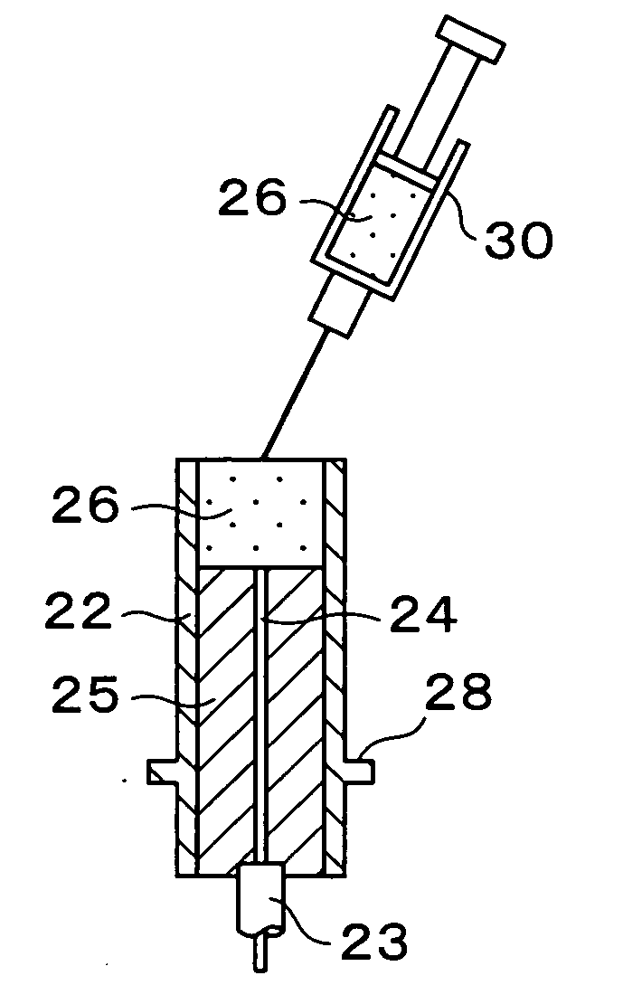
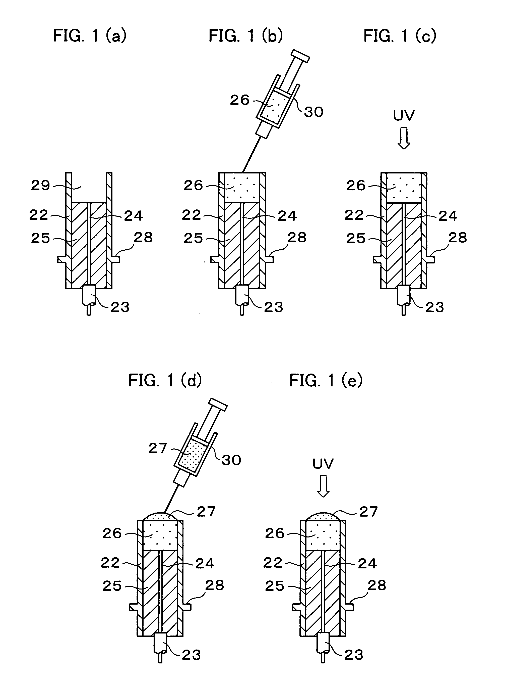
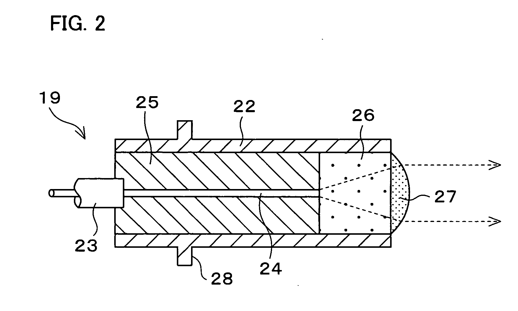
[0069] First, after an ultraviolet hardening resin MP121 (hardened resin refraction index; 1.55, produced by Mitsubishi Rayon Co., Ltd.) was injected as a first resin into a resin-injection portion of an optical fiber connector, ultraviolet rays were irradiated onto the first resin to harden the first resin. Next, an ultraviolet hardening resin UT1059 (hardened resin refraction index; 1.58, produced by Mitsubishi Rayon Co., Ltd.) was injected, as a second resin, on the first resin in order to form a pre-lens. Next, while a wave front aberration of light transmitting the pre-lens was measured with a shack hartmann wave front instrument, the ultraviolet rays were irradiated, when the wave front aberration got close to 0, in order to harden the second resin to produce a collimator lens of the optical fiber connector. The wave front aberration of the collimator lens obtained was not more than 1λ (λ: 1.3 μm), and a lens length was 2.8 mm. Note that, there were substantially no difference...

second example

[0070] A collimator lens of an optical fiber connector was produced in the same way as the First Example except that an ultraviolet hardening resin MP121 (hardened resin refraction index; 1.55, produced by Mitsubishi Rayon Co., Ltd.) was used as a first resin and a second resin. A wave front aberration of the collimator lens obtained was about 2λ, and a lens length was 2.8 mm. Note that, there were substantially no difference between the wave front aberration of the unhardened collimator lens and the wave front aberration of the hardened collimator lens.


PUM

PropertyMeasurementUnit
Waveaaaaaaaaaa
Refractionaaaaaaaaaa

Abstract

The production method for an optical fiber connector includes the steps of: injecting and hardening a first resin (26) into a resin-injection portion (29) of a connector body (22), the first resin (26) being a light hardening resin or a heat hardening resin; forming a pre-lens by further injecting a second resin (27) on the hardened first resin (26), the second resin (27) being the light hardening resin or the heat hardening resin; and forming a lens by hardening the second resin (27). In this way, it is possible to provide a production method for an optical lens by which influences by volume shrinkage of a resin are decreased, a lens surface can be formed with high accuracy and the product can be made with high quality.

Description

TECHNICAL FIELD [0001] The present invention relates to a production method for an optical lens, and more particularly, to the production method for an optical lens which can be suitably used for an optical fiber connector which is a terminal portion structure of an optical fiber having a small-diameter core whose diameter is about 5 to 10 microns, and to a production method for the optical fiber connector. BACKGROUND ART [0002] In recent years, a Single-Mode type (SM type) glass optical fiber is widely used for a long-distance trunk line, and it is targeted to build an information network by using this kind of optical fiber. By the way, a core diameter of the SM type optical fiber is 5 to 10 microns, which is extremely thin. Therefore, means for connecting and branching the optical fiber with high accuracy is needed in setting in the optical fiber. [0003] Therefore, a high-accuracy optical fiber connector 1 shown in FIG. 4 has been used, for example. In the optical fiber connector ...

Claims


Application Information

Patent Timeline
IPC IPC(8): G02B6/36B29C39/02B29C39/10B29C39/12B29C39/40B29D11/00B29K101/10B29L11/00G02B3/00G02B6/32G02B6/42
CPCB29C39/025B29C39/10G02B6/32B29D11/0075B29L2011/00B29D11/00365
Inventor JITSUNO, TAKAHISATOKUMURA, KEI
Owner JAPAN SCI & TECH CORP
Why Eureka
Try Eureka