Acoustic isolator between downhole transmitters and receivers

a technology of acoustic tool and transmitter, which is applied in the direction of seismology for waterlogging, instruments, borehole/well accessories, etc., to achieve the effects of reducing cutoff frequency, high tensile strength, and high tensile strength

Active Publication Date: 2005-08-04
SCHLUMBERGER TECH CORP
View PDF10 Cites 41 Cited by
  • Summary
  • Abstract
  • Description
  • Claims
  • Application Information

AI Technical Summary

Benefits of technology

[0010] The present invention meets the above-described needs and others. Specifically, the present invention provides apparatus and methods for isolating acoustic transmitters and receivers while also providing high tensile strength. The present invention utilizes a mass-spring mechanical filter to attenuate wave propagation through acoustic logging tools. The mass-spring mechanical filter has a high tensile strength and is operable in high temperature and high pressure environments. The mass-spring mechanical filter may be modular, with several stages connected together. The multiple stages provide a lower cutoff frequency than previously available.

Problems solved by technology

However, the first ball joint does not permit axial rotation, thus providing the alignment necessary for accurate dipole measurements.

Method used


Image

  • Acoustic isolator between downhole transmitters and receivers
  • Acoustic isolator between downhole transmitters and receivers
  • Acoustic isolator between downhole transmitters and receivers

Examples


Embodiment Construction

[0021] Illustrative embodiments and aspects of the invention are described below. It will of course be appreciated that in the development of any such actual embodiment, numerous implementation-specific decisions must be made to achieve the developers' specific goals, such as compliance with system-related and business-related constraints, that will vary from one implementation to another. Moreover, it will be appreciated that such a development effort might be complex and time-consuming, but would nevertheless be a routine undertaking for those of ordinary skill in the art having the benefit of this disclosure.

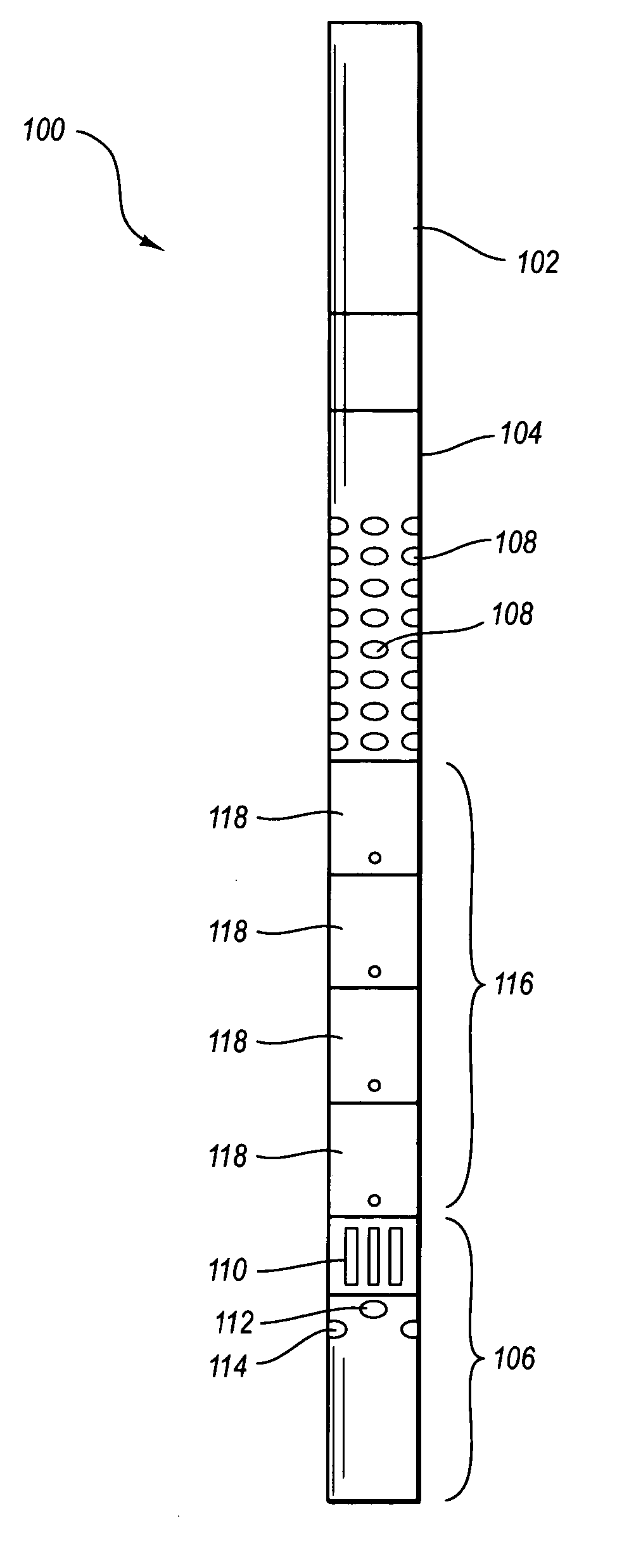
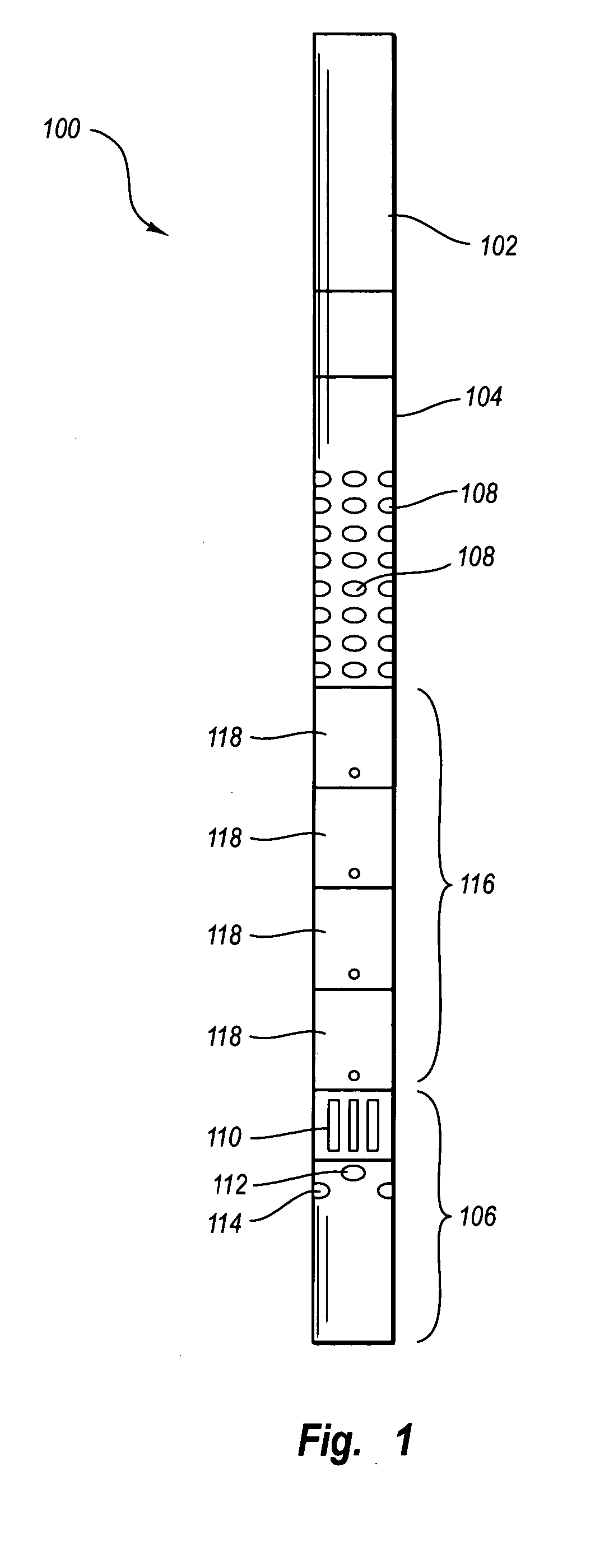
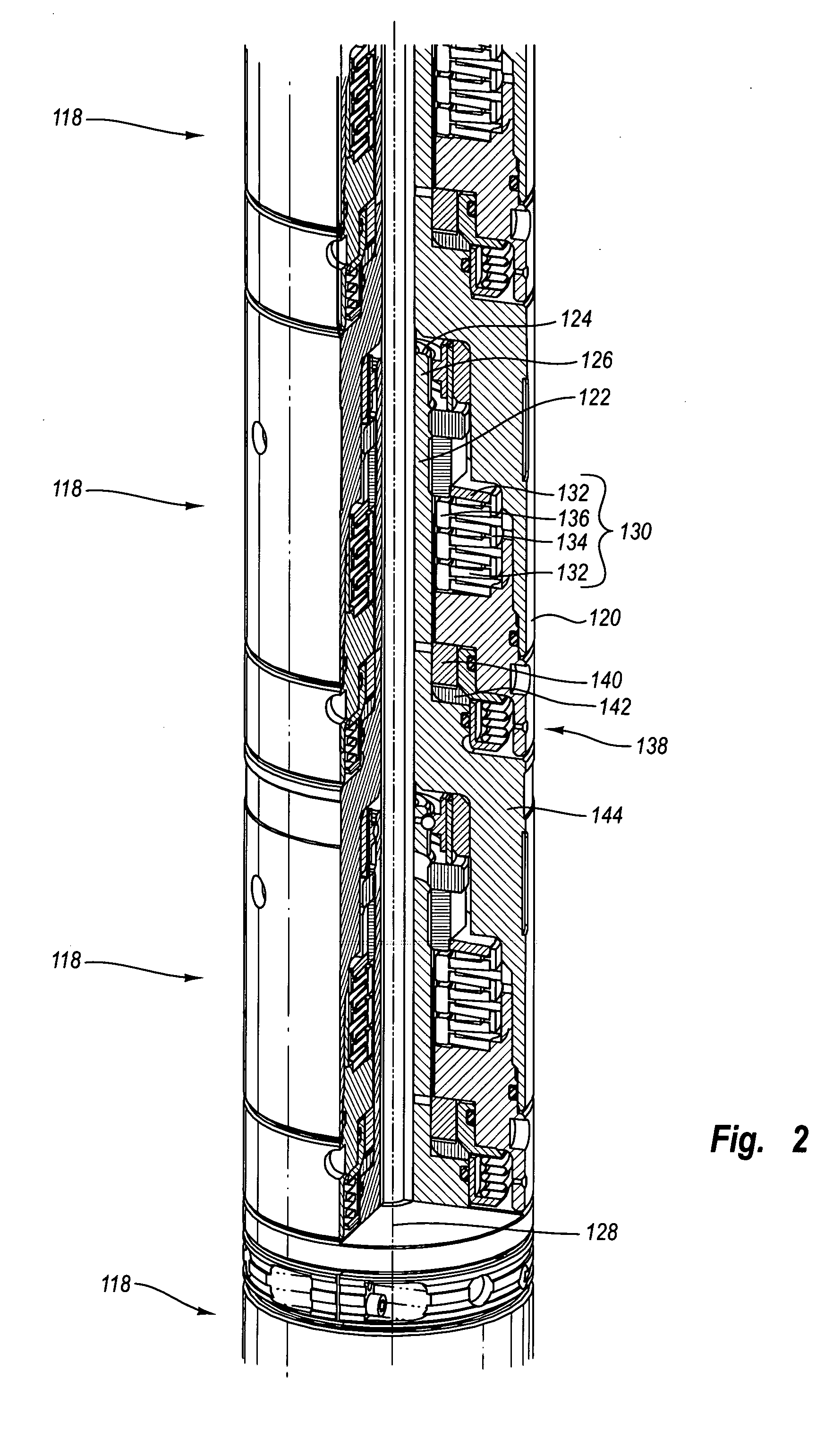
[0022] The present invention contemplates acoustic isolation between transmitters and receivers of acoustic tools, particularly sonic logging tools. Historically there has been some use of sonic isolators between transmitters and receivers, but the prior isolators tend to weaken the logging tool string, sometimes breaking at the isolator while still downhole. In addition, pr...


PUM


Abstract

Apparatus and methods for acoustically isolating logging tool receiver and transmitter sections. One or more modular isolators is arranged between the receiver and transmitter sections. The modular isolators comprise a high tensile strength while also providing for a high wave attenuation level. The modular isolators are mechanical mass-spring systems capable of absorbing acoustic waves propagating along the logging tool. The mass is a swinging sleeve, and the spring includes a Belleville spring stack. The use of the strong modular isolators provides acoustic isolation between the transmitters and receivers for the complete sonic frequency band at multiple modes.

Description

FIELD OF THE INVENTION [0001] The present invention relates generally to methods for investigating subsurface formations using sonic measurements made in a borehole. More particularly, this invention is directed to methods and apparatus for acoustically isolating between transmitters and receivers of a downhole acoustic tool. BACKGROUND OF THE INVENTION [0002] The generation and recording of borehole acoustic waves is a key measurement employed in oilfield wireline logging. Many borehole tools and methods are currently available for taking acoustic measurements. Some tools include a single source of sonic waves and two or more receivers; however, most of the tools now include many receivers arranged in an array. While the currently available acoustic tools are useful in providing a large range of information regarding the adjacent formation and the borehole parameters, a primary use of acoustic borehole measurements is the estimation of compressional wave formation slowness. [0003] ...

Claims


Application Information

Patent Timeline
Patent Type & Authority Applications(United States)
IPC IPC(8): G01V1/52
CPCG01V1/523
Inventor SUGIYAMA, HITOSHI
Owner SCHLUMBERGER TECH CORP
Why Eureka
Try Eureka