
Hydrostatic drive apparatus for a road vehicle

a technology of driving apparatus and road vehicle, which is applied in the direction of gas pressure propulsion mounting, propulsion parts, transportation and packaging, etc., can solve the problems of high cost of vehicles, over-heavy and only marginally efficient, and heavy weight of the drivetrain

Inactive Publication Date: 2005-08-04
JOHNSON WELDED PRODS
View PDF24 Cites 42 Cited by
  • Summary
  • Abstract
  • Description
  • Claims
  • Application Information

AI Technical Summary

Benefits of technology

"The present invention is a vehicle that uses hydraulic machines to drive its wheels. It has a gas engine that drives a hydraulic pump / motor, which in turn drives the wheels. It also has an electric motor / generator that drives a hydraulic pump / motor, which powers accessories like power steering, air compressor, and supercharger. A controller regulates the capacity of the hydraulic pump / motor and controls its functions to either crank the engine or charge the battery. During engine operation, the hydraulic pump / motor also powers the accessories. The technical effect of this invention is an improved vehicle that utilizes hydraulic machines for efficient drive functions and powering of accessories."

Problems solved by technology

While this configuration has become standardized in the trucking industry, it necessarily results in vehicles that are costly, overly-heavy and only marginally efficient.
For example, the drivetrain weight is very heavy, the engine frequently runs at high fuel consumption operating points, and the accessory pumps and motors are driven continuously and at variable engine-related speeds.

Method used


Image

  • Hydrostatic drive apparatus for a road vehicle
  • Hydrostatic drive apparatus for a road vehicle
  • Hydrostatic drive apparatus for a road vehicle

Examples


Embodiment Construction

[0007] The present invention is disclosed herein primarily in the context of a roadway vehicle such as a truck equipped with a continuously variable hydrostatic drive. However, it will be understood that the invention is also applicable to other types of vehicles.

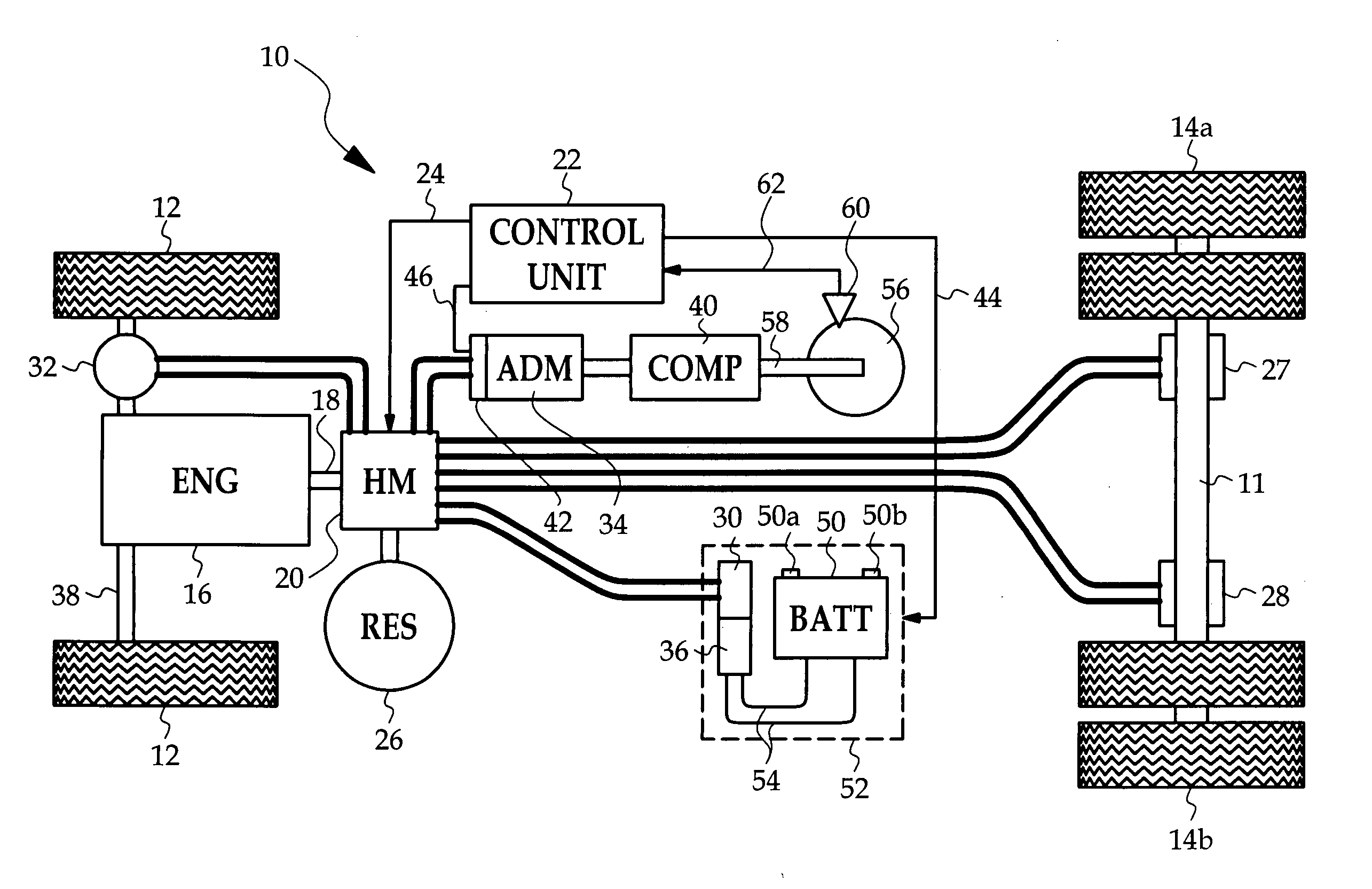
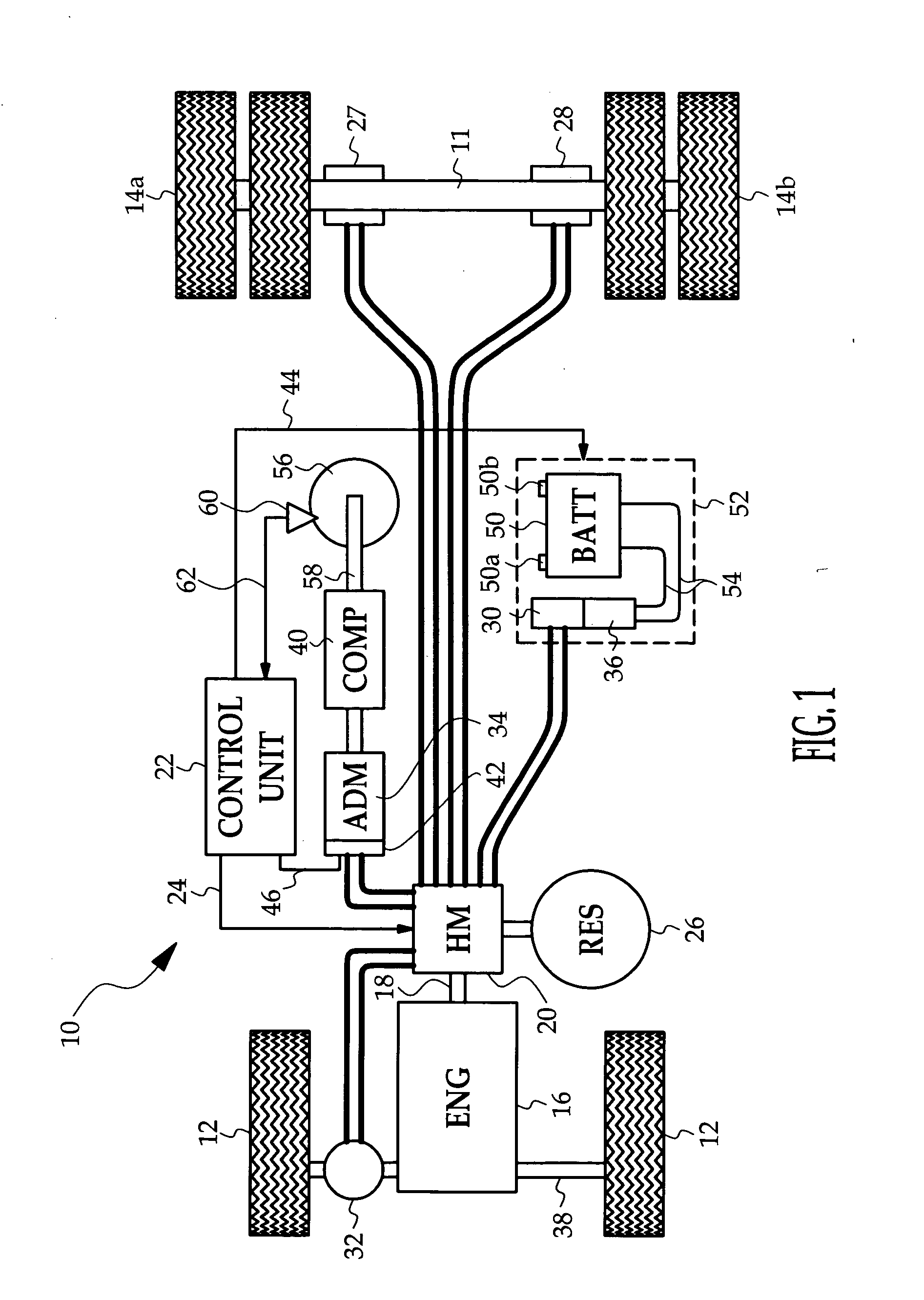
[0008] Referring to FIG. 1, the reference numeral 10 generally designates a road vehicle such as a heavy-duty truck. The various components depicted in FIG. 1 are mounted on a chassis including a pair of longitudinal frame rails which are not shown and the frame cross-member 11 which is shown. The vehicle has front wheels / tires 12, and at least one set of rear wheels / tires 14a, 14b. The engine (ENG) 16, which is typically a turbocharged diesel engine, includes an output shaft 18 coupled to drive a variable capacity hydraulic machine (HM) 20. The hydraulic machine 20 is operated under the control of a microprocessor-based control unit 22, as indicated by the line 24. During operation of the engine 16, the control unit 22 op...


PUM


Abstract

A road vehicle utilizes hydraulic machines for primary and accessory vehicle drive functions. An internal combustion engine directly drives a first variable capacity hydraulic machine selectively operable as pump or motor, an electric machine electrically coupled to a storage battery is selectively operable as motor or generator and is mechanically coupled to a second hydraulic machine operable as pump or motor, and at least one hydraulic drive motor is coupled to a vehicle drive wheel. A controller regulates the capacity of the first hydraulic machine, and controls the functionality of the first and second hydraulic machines to selectively crank the engine or charge the storage battery. The first hydraulic machine also supplies hydraulic fluid to accessory drive motors including a power steering drive motor, an air compressor drive motor and a supercharger drive motor.

Description

TECHNICAL FIELD [0001] The present invention relates to road vehicles such as semi-tractor-trailers, and more particularly to hydrostatic drive arrangements for efficient operation of the vehicle engine and accessories. BACKGROUND OF THE INVENTION [0002] Heavy-duty road vehicles such as straight trucks and semi-tractor trailers are customarily equipped with a powerful diesel engine that mechanically drives not only the vehicle but also a generator or alternator and various accessory pumps for braking and steering systems. In a typical configuration, the engine output shaft is coupled to the vehicle drive wheels through a manual or automatic transmission and one or more differential gearsets, and a power-take-off or belt-drive is used to drive the accessory systems. While this configuration has become standardized in the trucking industry, it necessarily results in vehicles that are costly, overly-heavy and only marginally efficient. For example, the drivetrain weight is very heavy, ...

Claims


Application Information

Patent Timeline
Patent Type & Authority Applications(United States)
IPC IPC(8): B60K6/12B60K17/00
CPCB60K6/12Y02T10/6208B60K17/10Y02T10/62B60K2006/126B60K2006/268
Inventor JOHNSON, TRUMAN G.
Owner JOHNSON WELDED PRODS
Learn More