Edge effects treatment for crystals

a technology of edge effects and crystals, applied in the field of reduction or elimination of edge effects in optical elements, can solve the problems of serious reduction in the ability to accurately determine the position of such events, edge effects, and the reduction of the measured positional accuracy of imaging data, so as to reduce the edge effect and the loss of positional accuracy

Inactive Publication Date: 2005-08-04
HIGHBROOK HLDG
View PDF14 Cites 35 Cited by
  • Summary
  • Abstract
  • Description
  • Claims
  • Application Information

AI Technical Summary

Benefits of technology

[0011] Methods and apparatus are provided to reduce edge effects, such as loss of positional accuracy due to edge reflection, in optical elements suc

Problems solved by technology

A problem in scintillation imaging is that reflections from the edge of the scintillator will reduce the measured positional accuracy of imaging data, particularly for scintillation events occurring close to the edge of the scintillator.
Light from scintillation events occurring near an edge will be reflected from that edge, causing a serious reduction in ability to accurately determine the position of such events.
This dead zone or “edge effect” reduces the effective usable portion of the scintillator.
In addition, the presence of this unusable region at the periphery of the detector prevents the detector from being positioned optimally in many medical applications, for example breast and brain scintig

Method used


Image

  • Edge effects treatment for crystals
  • Edge effects treatment for crystals
  • Edge effects treatment for crystals

Examples


Embodiment Construction

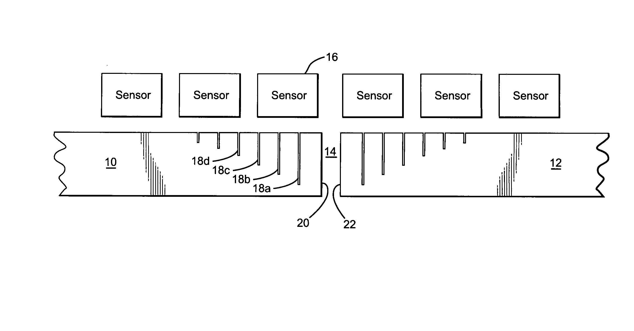
[0034] In examples discussed below, the term “crystal” is used for convenience to refer to a scintillation material. However, examples discussed here apply equally to non-crystalline scintillators. Also, in examples discussed below, light guides are provided by grooves cut into one or more surface of the crystal (or associated window). As discussed in more detail below, other forms of light guide can also be used, for example, reflective films.

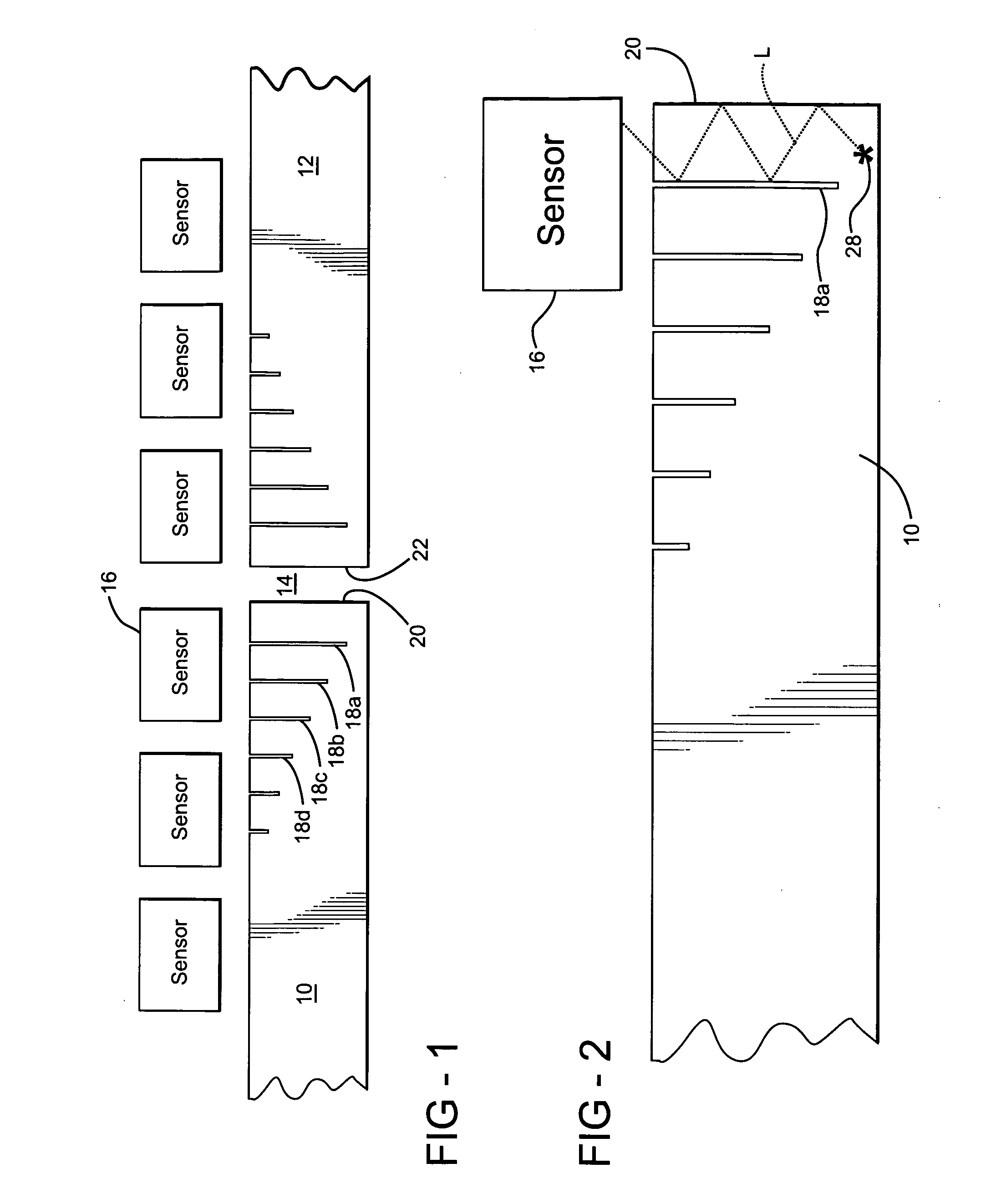
[0035]FIG. 1 shows a portion of a first crystal 10, a portion of a second crystal 12, a crystal gap 14 between the two crystals, a plurality of sensors such as sensor 16, a plurality of grooves in the light emitting face of each crystal, such as grooves 18a-18d, a first crystal edge 20, and a second crystal edge 22.

[0036] As drawn, the lower surface of the crystal 10 is the radiation receiving face, and the upper surface of the crystal is the light emitting face. This convention will be followed (for convenience only) through the various fig...


PUM


Abstract

A scintillator, for use in a radiation imaging device, has a light-emitting face, a radiation receiving face, and a perimeter extending between the light-emitting face and the radiation receiving face, the perimeter including an edge, the edge having an edge thickness. The scintillator emits scintillation light from the light emitting face in response to radiation incident on the radiation receiving face. The scintillator has one or more light guides formed within a peripheral region of the scintillator proximate to the edge. The light guides can improve the positional accuracy of a radiation imaging device including the scintillator.

Description

REFERENCE TO RELATED APPLICATION [0001] This application claims priority of U.S. Provisional Patent Application Ser. No. 60 / 523,765 filed Nov. 20, 2003, the entire contents of which are incorporated herein by reference.FIELD OF THE INVENTION [0002] The invention relates to improved apparatus and methods relating to reduction or elimination of edge effects in optical elements, for example, scintillators. BACKGROUND OF THE INVENTION [0003] A scintillation material, or scintillator, produces light in response to incident radiation, typically ionizing radiation such as gamma rays or x-rays. Such a material can be a crystal such as thallium-doped sodium iodide, NaI(Tl), or a non-crystalline material such as a plastic. [0004] Radiation detectors using scintillators include gamma cameras, x-ray detectors, and other radiation imaging or sensing devices. The scintillator generally has a radiation receiving face on which radiation such as gamma rays are incident. The scintillator has a light ...

Claims


Application Information

Patent Timeline
IPC IPC(8): G01TG01T1/24
CPCG01T1/20
Inventor JUNI, JACK E.
Owner HIGHBROOK HLDG
Why Eureka
Try Eureka