Device and system for toll payment
- Summary
- Abstract
- Description
- Claims
- Application Information
AI Technical Summary
Benefits of technology
Problems solved by technology
Method used
Image
Examples
first embodiment
[0028] (First Embodiment)
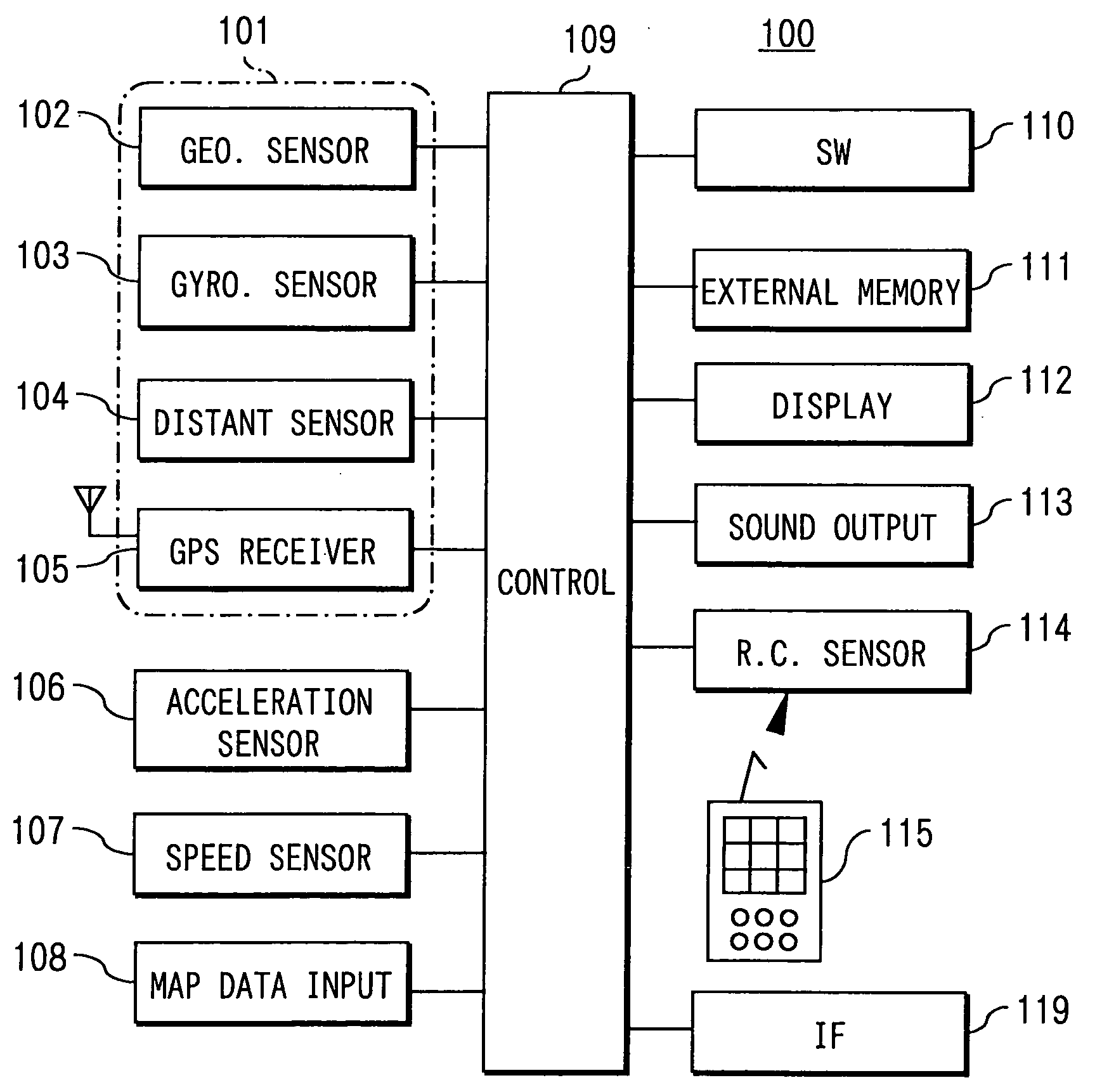
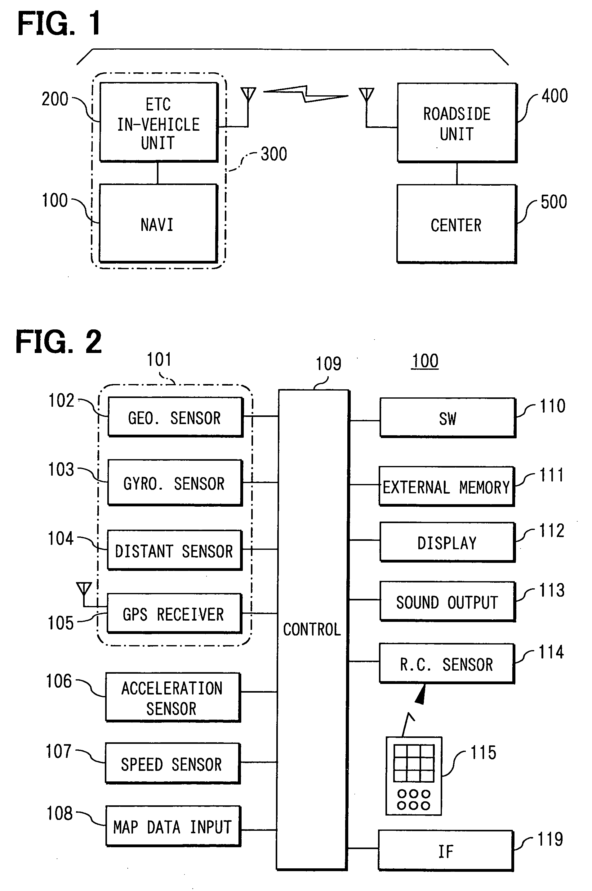
[0029] A toll payment system of a first embodiment includes a toll payment device constituted by a navigation device 100 and an ETC in-vehicle unit 200, a roadside unit 400 that is installed at an ETC gate communicating with the ETC in-vehicle unit 200 via a road-vehicle communications, and a center 500 that interfaces with the roadside unit 400.
[0030] The ETC in-vehicle unit 200 is, as known, for automatically paying a toll using bi-directional communications with the roadside unit installed at the ETC gate on a toll road. The ETC in-vehicle unit 200 accepts an ETC card being a credit card (not shown) inserted into it to thereby capable of pay the toll. This ETC card includes a user ID that is uniquely assigned to each user. When a subject vehicle passes through an ETC gate, the user ID is sent to the roadside unit 400 to thereby cause a user who pays the toll to be identified.
[0031] The ETC in-vehicle unit 200 includes the following functions. First, a c...
modification 1
[0070] Modification 1
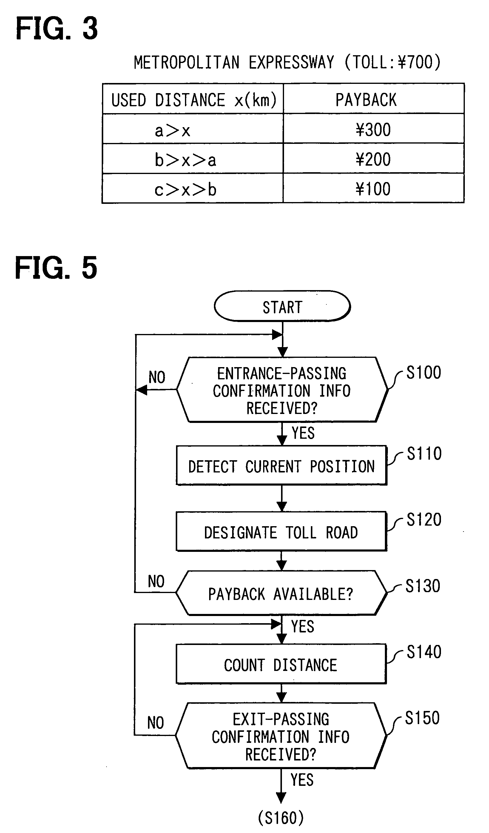
[0071] In the toll payment system of the first embodiment, the followings are sent to the center 500 in the payback process: the start time of using the toll road; the name of the toll road; the paid toll; the interchange names of the entrance point and the exit point; and the payback information including the route information having the used distance. However, for instance, when a discount payment system is introduced that discounts a toll based on a use frequency to a user or a commuter who uses the same route on the toll road, use frequency information can be also sent by being attached to the payback information. This use frequency information indicating the frequency of using the same route can be obtained by referring to the payback information stored in the external memory 111.
[0072] Thus, a partial payback can be received; further, a discount to the toll can be received based on the use frequency when a discount payment system according to the use freq...
modification 2
[0073] Modification 2
[0074] In the toll payment system of the first embodiment, the followings are sent to the center 500 in the payback process: the start time of using the toll road; the name of the toll road; the paid toll; the interchange names of the entrance point and the exit point; and the payback information including the route information having the used distance. However, for instance, when a payment system is introduced that increases a payback ratio of a toll to a vehicle mounted with an ETC-associated navigation device of this embodiment that is associated with the ETC in-vehicle unit 200, information indicating that the ETC-associated navigation device is being mounted can be also sent by being attached to the payback information.
[0075] Thus, in addition to receiving the partial payback, an additional payback can be received when the payment system is introduced that increases a payback ratio of a toll to a vehicle mounted with an ETC-associated navigation device. As...
PUM
 Abstract
Description
Claims
Application Information
 - R&D
- Intellectual Property
- Life Sciences
- Materials
- Tech Scout
- Unparalleled Data Quality
- Higher Quality Content
- 60% Fewer Hallucinations
Browse by: Latest US Patents, China's latest patents, Technical Efficacy Thesaurus, Application Domain, Technology Topic, Popular Technical Reports.
© 2025 PatSnap. All rights reserved.Legal|Privacy policy|Modern Slavery Act Transparency Statement|Sitemap|About US| Contact US: help@patsnap.com


