

Optical system, and image pick-up apparatus using the same
- Summary
- Abstract
- Description
- Claims
- Application Information
AI Technical Summary
Benefits of technology
Problems solved by technology
Method used
Image

Examples
first embodiment
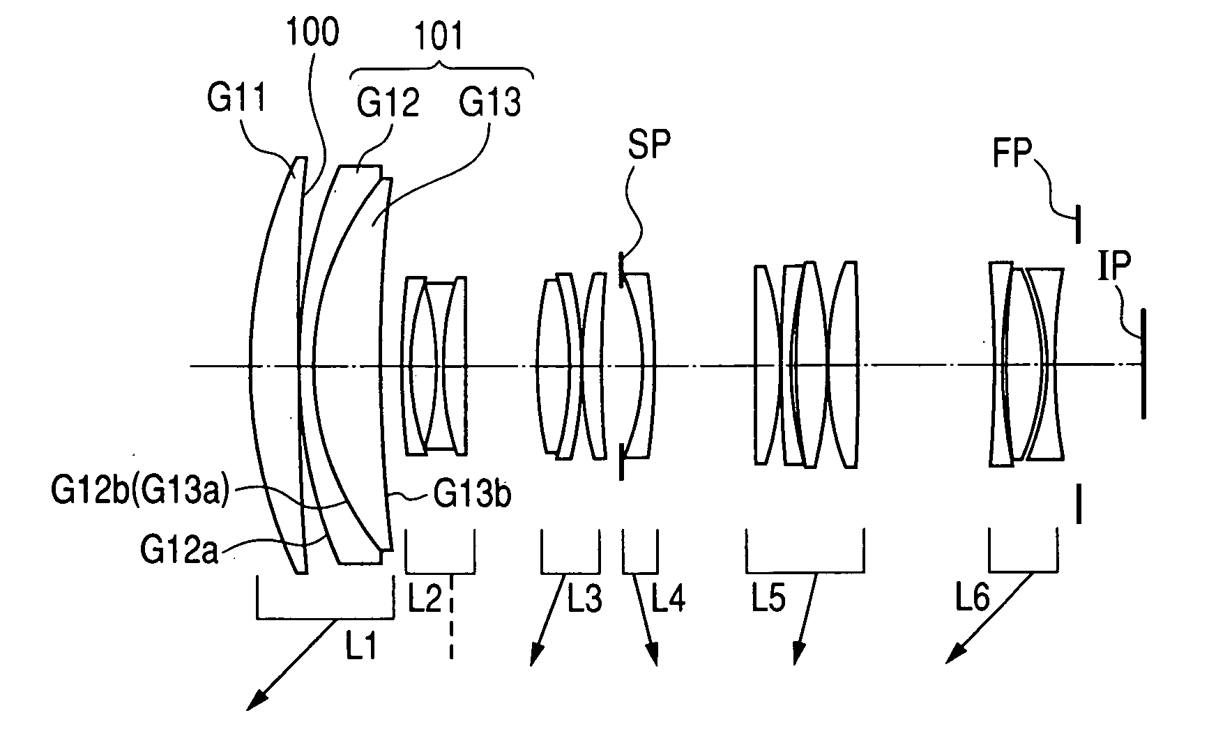
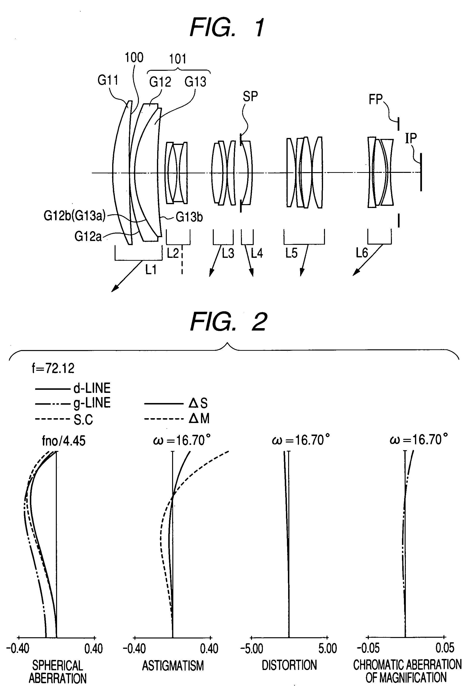
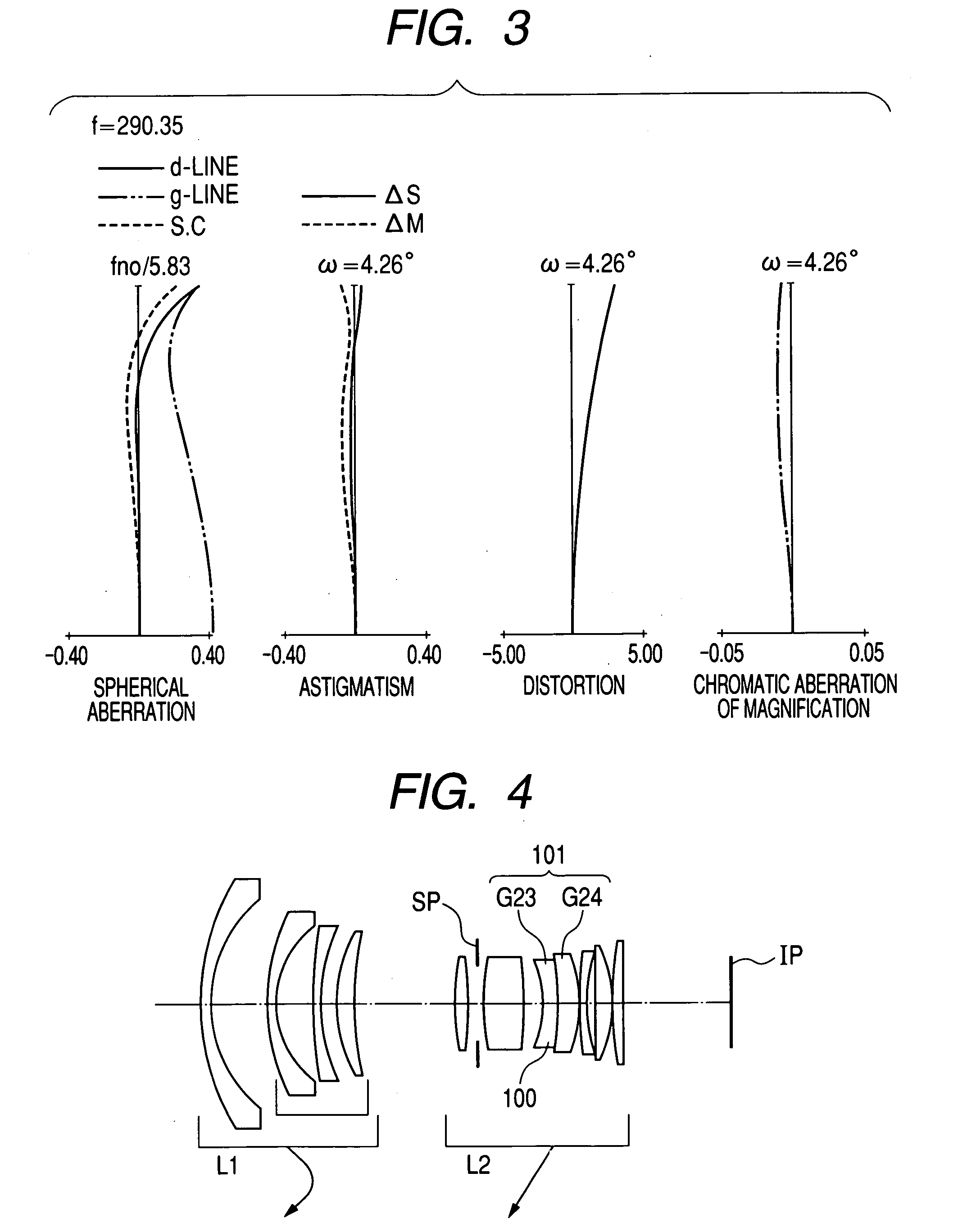
[0028] The zoom lens of the first embodiment is a shooting lens system to be used in an image pick-up apparatus. In the lens cross-sectional view of FIG. 1, its left side is an object side (a front side), and its right side is an image side (a rear side). In the lens cross-sectional view of FIG. 1, L1 represents a first lens unit having positive refractive power (optical power is equal to a reciprocal of a focal length), L2 represents a second lens unit having negative refractive power, L3 represents a third lens unit having positive refractive power, L4 represents a fourth lens unit having negative refractive power, L5 represents a fifth lens unit having positive refractive power, and L6 represents a sixth lens unit having negative refractive power. SP designates an aperture stop, and the aperture stop SP is disposed on an object side of the fourth lens unit L4. FP designates a flare cut stop, and IP designates an image plane, which corresponds to an image pick-up plane of a solid-...
second embodiment
[0052]FIG. 4 is a lens cross-sectional view illustrating an optical system of the second embodiment according to the present invention. In FIG. 4, a zoom lens is at its wide-angle end.
[0053] In the lens cross-sectional view of FIG. 4, L1 represents a first lens unit having negative refractive power, and L2 represents a second lens unit having positive refractive power. While an interval between lens units L1 and L2 is reduced, zooming from the wide-angle end to the telephoto end is performed by moving the lens units L1 and L2 toward an object side as indicated by arrows.
[0054] SP designates an aperture stop. The aperture stop SP moves integrally with the second lens unit L2 during zooming. IP designates an image plane.
[0055] In the second embodiment, a diffractive optical element 101 is constituted by forming a diffraction grating made of ultraviolet-radiation curing resin on an image-side lens surface of a lens G24 constituting the second lens unit L2. Further, ultraviolet-radiat...
third embodiment
[0056]FIG. 5 is a lens cross-sectional view illustrating an optical system of the third embodiment according to the present invention. In FIG. 5, a zoom lens is at its wide-angle end.
[0057] In the lens cross-sectional view of FIG. 5, L1 represents a first lens unit having negative refractive power, L2 represents a second lens unit having positive refractive power, and L3 represents a third lens unit having negative refractive power. SP designates a stop. IP designates an image plane. FP designates a flare cut stop.
[0058] In the zoom lens of the third embodiment, the first and second lens units L1 and L2 are moved toward an object side as indicated by arrows during zooming from the wide-angle end to the telephoto end.
[0059] In the third embodiment, a diffractive optical element 101 is constituted by forming a diffraction grating made of ultraviolet-radiation curing resin on an image-side lens surface of a lens G26 constituting the second lens unit L2. Further, a light blocking mean...
PUM
 Abstract
Description
Claims
Application Information