Expandable collet anchor system and method

a collet and collet technology, applied in the direction of screws, threaded fasteners, manufacturing tools, etc., can solve the problems of time-consuming and labor-intensive riveting installation, requiring expensive specialized equipment, and subsequent tightening of the floor panel to the underlying structur

Inactive Publication Date: 2005-08-04
MCCLURE TRAVIS D
View PDF15 Cites 72 Cited by
  • Summary
  • Abstract
  • Description
  • Claims
  • Application Information

AI Technical Summary

Benefits of technology

[0027] A variety of means are available for counteracting induced rotation of the collet body. Presuming a closely matched collet body and insertion aperture (whether as determined by the part aperture or by an auxiliary structure such as a sleeve insert), one series of embodiments relies upon the incorporation of a non-circular cross section portion of the collet body. A simple illustration of this form is a key and slot arrangement where the key may be present on a portion of the collet and the slot formed in the piece to be attached (or an auxiliary structure such as a sleeve insert), or vice ve

Problems solved by technology

Said torque rotates the countersunk screw with respect to the nut-plate element, thus causing subsequent tightening of the floor panel to the underlying structure.
However, these existing methods often are accompanied by substantial detrimental consequences that result in costly reworks and delays.
However, the installation of riveted on nut-plates is time consuming and requires expensive specialized equipment.
Special care must be taken during this process not to misalign or mis-locate the rivets or the rivet holes as such misalignment can result in a variety of problems, e.g., replacement of the entire structure, an extremely expensive process.
Unfortunately, the locator tab has a sharp edge that scratches the surface of the underlying structure every time a clip nut is removed or installed, even when the underlying structure is treated with anti-corrosion coatings.
In addition, the back of the “U”-shape, which acts as a torque reactor, nicks and rubs against the underlying structure, further providing corr

Method used


Image

  • Expandable collet anchor system and method
  • Expandable collet anchor system and method
  • Expandable collet anchor system and method

Examples


Embodiment Construction

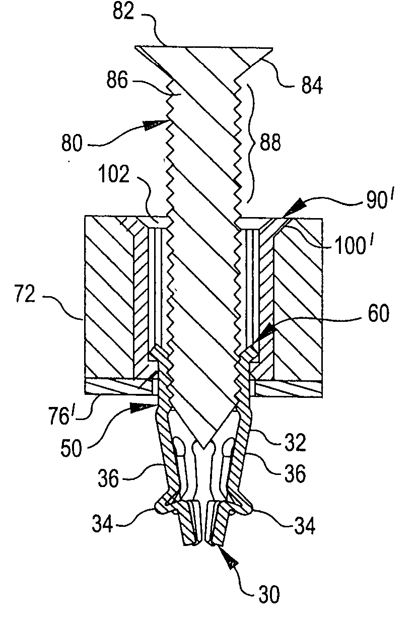
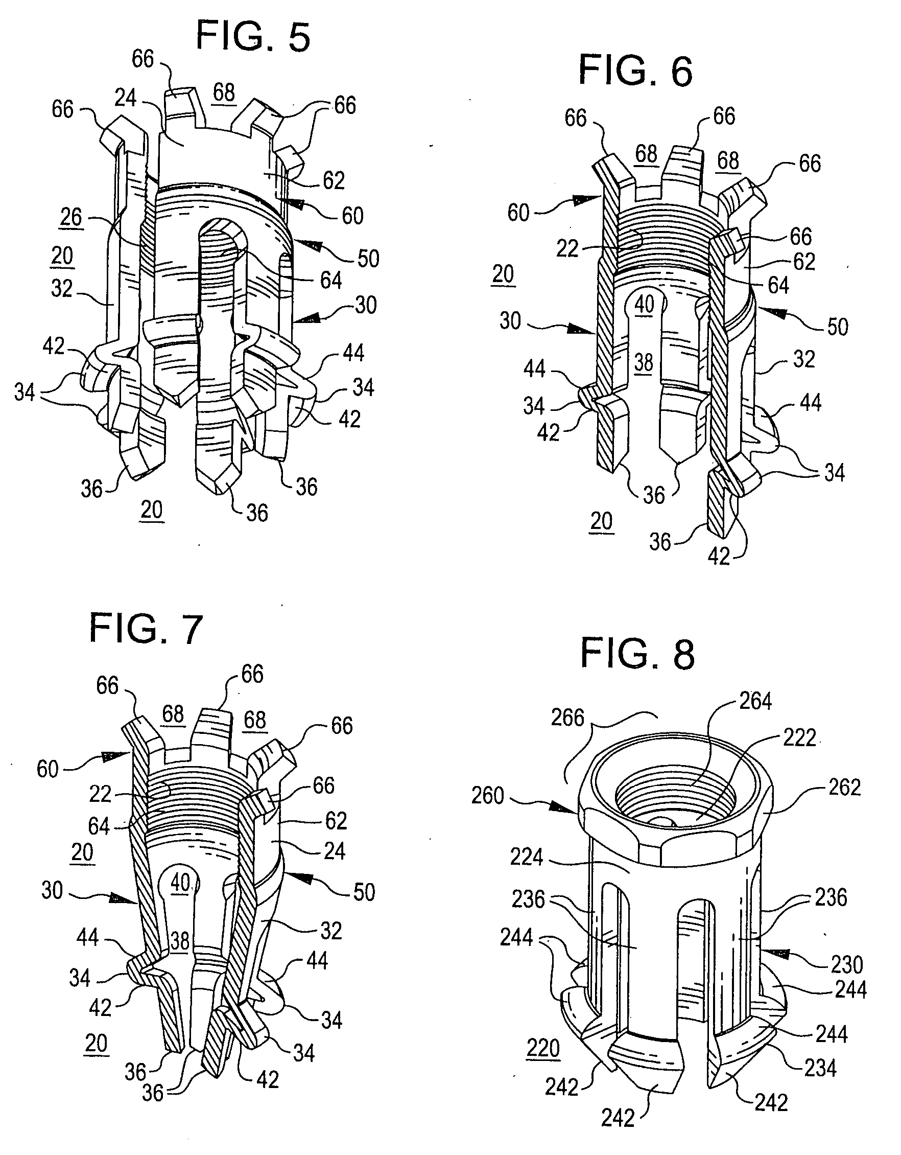
[0055] Turning then to the several Figures wherein like numerals indicate like parts, and more particularly to FIGS. 5-7, a first embodiment of a collet body is shown. Unless otherwise noted, any described collet body or collet system is intended to secure at least two objects together, i.e., fasten at least two objects together, each having a generally circular aperture, to form a single attachment. An exception to this premise relates to FIGS. 17-22 wherein a rectilinear aperture is preferred and FIGS. 23-28 wherein a stud is fixedly attached to one object and operates to anchor a second object thereto.

[0056] Returning then to FIGS. 5-7, collet body 20 can be formed from any material suitable for its intended application including metals, polymers, and composites. In the illustrated embodiment, collet body 20 is formed from metal and comprises the following portions and elements: first end 30; first wall portion 32, which includes protruding portion 34 and defines fingers 36; mid...


PUM

PropertyMeasurementUnit
Thicknessaaaaaaaaaa
Diameteraaaaaaaaaa
Surfaceaaaaaaaaaa

Abstract

An expandable collet body and anchor system incorporating a collet body anti-rotation feature and preferably collet body translation arresting means are disclosed. The collet body includes a first end, a first wall portion having at least two fingers, a second end including a head, a second wall portion, an annular protrusion and anti-rotation means where the anti-rotation means engages with an auxiliary structure defining a hole having an internal surface adapted to translationally accept the collet body and operatively function with the collet body anti-rotation means. The auxiliary may include a work piece to be optionally joined to another structure or a sleeve insert locatable in a hole defined by a work piece. Because the collet body is relatively free to translate within the auxiliary structure, a wide spectrum of work piece depths can be engaged with a single length collet body with the use of a stud to radially expand the fingers, thereby engaging a distal structure.

Description

[0001] Priority to and benefit of co-pending PCT application number PCT / US03 / 02925 filed 31 Jan. 2003, which claims priority to U.S. provisional application No. 60 / 357,292, is hereby claimed.BACKGROUND OF THE INVENTION [0002] In the field of non-permanent floor panel attachment, a nut and bolt combination has almost always been employed. A simple method involves directly passing a threaded bolt (or stud) through the front side of a passageway between the floor panel and underlying structure, and attaching a likewise threaded nut located on the backside of the passage to the bolt (stud) (in the case of a threaded stud, nuts are positioned at the front and backside of the passage to engage with the stud). Torque is then applied to the nut(s) with respect to the bolt (stud) in order to tighten the floor panel to the underlying structure. [0003] A more sophisticated installation uses a potted-in insert installed in an enlarged passageway in the floor panel, the insert having an internal...

Claims


Application Information

Patent Timeline
IPC IPC(8): F16B13/04B64C1/00F16B13/06F16B19/10F16B33/00F16B37/04
CPCF16B19/1081F16B33/002Y10T29/49963B23P23/00F16B37/043
Inventor MCCLURE, TRAVIS D.
Owner MCCLURE TRAVIS D
Why Eureka
Try Eureka