Singlestage and multistage electromagnetic revolutionary piston pump

a revolutionary, piston pump technology, applied in the field of piston pumps, can solve the problems of increasing working cost, reducing work efficiency, and affecting the operation of the whole system, so as to reduce the number of pump parts used and the size of the pump, and improve the airflow

Inactive Publication Date: 2005-08-04
DELTA ELECTRONICS INC
View PDF1 Cites 7 Cited by
  • Summary
  • Abstract
  • Description
  • Claims
  • Application Information

AI Technical Summary

Benefits of technology

[0009] Another object of the invention is to effectively increase airflow and pressure and to improve reciprocating piston pump efficiency.
[0010] Another object of the invention is to effectively reduce number of parts in electromagnetic reciprocating piston pumps and to make the reciprocating pump size smaller.
[0017] Through the design of the invention, the electromagnetic revolutionary piston pump is able to: 1. have continuous air pressure and increased airflow; 2. avoid the usage of parts like back-pressure valve, and thus effectively reduces the number of pump parts used and the pump size; 3. lower the energy loss in the system, and hence increases work efficiency and reduces working cost.

Problems solved by technology

Secondly, an extra pressure storage tank is often needed for the pump to get a stable and continuous pressure.
Thirdly, the back-pressure valves constraining airflow direction, the intake valves, and the exhaust valves provided inside the reciprocating piston pump are made of many parts, which not only complicates the whole system but also makes the system difficult to maintain.
Fourthly, the friction produced during reciprocation of the piston consumes a large amount of kinetic energy of the piston, results in more energy provision for the piston, and thus leads to an increase in working cost and a decrease in work efficiency.

Method used


Image

  • Singlestage and multistage electromagnetic revolutionary piston pump
  • Singlestage and multistage electromagnetic revolutionary piston pump
  • Singlestage and multistage electromagnetic revolutionary piston pump

Examples


first embodiment

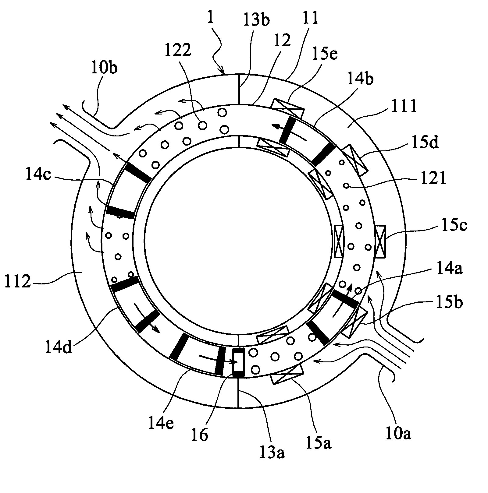
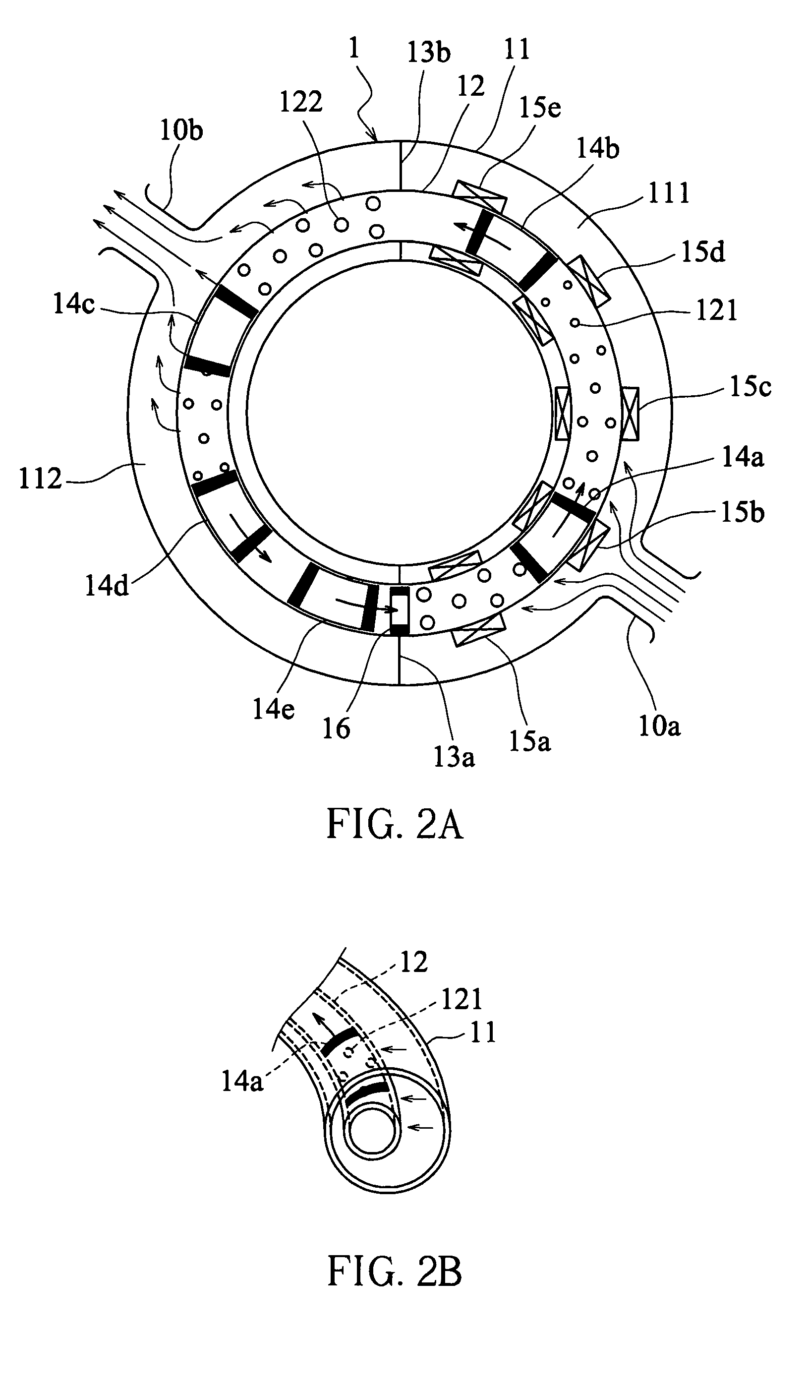
[0026] Referring to FIG. 2A and FIG. 2B, in a first embodiment, an electromagnetic revolutionary piston pump 1 includes a plastic outer doughnut tube 11, a copper inner doughnut tube 12, two annular separation plates 13a and 13b, five pistons 14a to 14e, and five sets of electromagnetic coils 15a to 15e.

[0027] The inner doughnut tube 12 is wrapped inside the outer doughnut tube 11, and the inner doughnut tube has a plurality of through holes 121 and 122 arranged on its' sidewall. The two annular separation plates 13a and 13b are placed inside the outer doughnut tube 11 but outside the inner doughnut tube 12, dividing the inner space of the outer doughnut tube 11 into two airproof spaces 111 and 112 that do not communicate with each other. The airproof space 111 connects an intake opening 10a closer to the annular separation plate 13a, and communicates with the space inside the inner doughnut tube 12 via the through holes 121. The airproof space 112 connects an exhaust opening 10b c...

second embodiment

[0035] Referring to FIG. 3, in a second embodiment, the airproof space 112 of electromagnetic revolutionary piston pump 1 can be further divided into 4 airproof spaces 113, 114, 115, and 116 by using other annular separation plates 13c, 13d, and 13e with the airproof spaces 113, 114, 115, and 116 connecting exhaust openings 10c, 10d, 10e, and 10f, respectively. In this way, one can get air with various pressures and airflows separately from the exhaust openings 10c, 10d, 10e, and 10f.

third embodiment

[0036] Referring to FIG. 4, in a third embodiment, a plurality of electromagnetic revolutionary piston pumps according to the invention can be connected in series to provide higher pressure of multistage and more airflow. For example, the exhaust opening of an electromagnetic revolutionary piston pump 1 is connected to the intake opening of an electromagnetic revolutionary piston pump 2, and the exhaust opening of the electromagnetic revolutionary piston pump 2 is connected to the intake opening of an electromagnetic revolutionary piston pump 3, and so on.

[0037] Since the pistons of the invention revolve inside the inner doughnut tube continuously, the invention can therefore generate continuous pressure without a backpressure valve and have the same pressure range as a conventional reciprocating pump. In addition, since the loss of magnetic energy in the invention relates only to the friction between pistons and the tube wall during the acceleration process, the loss of the electro...


PUM


Abstract

An electromagnetic revolutionary piston pump is disclosed. The electromagnetic revolutionary piston pump includes an inner tube, an outer tube, two annular separation plates, a plurality of pistons, and an electromagnetic coil. The inner tube has a plurality of first and second through holes, and it accommodates the abovementioned pistons to revolve inside. The outer tube has an intake opening and an exhaust opening, and it wraps the inner tube inside. In addition, the annular separation plates are disposed inside the outer tube for dividing the inner space of the outer tube into a first airproof space and a second airproof space. The first airproof space connects the intake opening and communicates the inner space of the first tube via the first through holes; the second airproof space connects the exhaust opening and communicates the inner space of the first tube via the second through holes. Moreover, the electromagnetic coil is mounted on the wall outside of the inner tube in the first airproof space for exerting magnetic force onto the pistons.

Description

BACKGROUND OF THE INVENTION [0001] (a) Field of the Invention [0002] The present invention relates to a piston pump and, more particularly, to an electromagnetic revolutionary piston pump. [0003] (b) Description of the Related Art [0004] An air pump is a device used to increase air pressure by reducing volume of the air. Air pumps are usually classified into three types—reciprocating, centrifugal, and axial-flow, and the reciprocating type is most commonly used due to its' ability to obtain a wide pressure range. [0005] A reciprocating pump is also called a reciprocating piston pump for that it has a piston reciprocating in a fixed space to compress air and thus increase pressure. Presently, electromagnetic force is often used to drive the piston, as illustrated in FIG. 1, to gain larger air pressure from the reciprocating piston pump. [0006] However, the reciprocating piston pump illustrated in FIG. 1 has the following disadvantages. Firstly, the pressure distribution is discontinu...

Claims


Application Information

Patent Timeline
Patent Type & Authority Applications(United States)
IPC IPC(8): F04B19/14F04B31/00F04B35/04
CPCF04B19/14F04B35/045F04B31/00
Inventor SHEN, DER-YOUNGYU, YUAN-YINGCHEN, LEE-LONGYEH, MING
Owner DELTA ELECTRONICS INC
Why Eureka
Try Eureka