Method for operating vehicle-mounted fuel cell stack

a fuel cell and stack technology, applied in the direction of hybrid vehicles, battery/fuel cell control arrangements, electrochemical generators, etc., can solve the problems of inability to easily dissipate or remove the fuel cell assembly is disclosed, and the heat produced in the fuel cell laminates b>201/b> cannot be easily dissipated or removed, etc., to achieve the effect of minimizing the cooling effect, effectively promoting, and reducing the cooling effect of b

Inactive Publication Date: 2005-08-04
HONDA MOTOR CO LTD
View PDF8 Cites 16 Cited by
  • Summary
  • Abstract
  • Description
  • Claims
  • Application Information

AI Technical Summary

Benefits of technology

[0009] The present invention characterized by performing the control to zero the allocated amount of the cooling air, via the air allocation mechanism, when the temperature measured by the temperature measurement step is lower than the preset standard operating temperature of the power generating cells. Particularly, during a startup period, for example, each of the cooling-air introduction openings is closed with each of the reacting-air introduction openings kept open and an air-sucking-in fan activated. Thus, the entire air introduced through the operation of the fan is caused to flow through the reacting-air introduction openings into the power generating cells, as the reacting air for reaction with the hydrogen, with a minimized cooling effect. As a consequence, the electric power generation reaction between the hydrogen and the oxygen in the air can be effectively promoted with a minimized cooling effect, so that the temperature of each of the power generating cells is allowed to readily rise as desired. In this way, the present invention can reduce the time necessary for the temperature of the power generating cells to increase up to a predetermined operating temperature level.
[0010] Further, the vehicle-mounted fuel cell stack operation method of the present invention is characterized by constantly (i.e., at the startup and subsequent periods) measuring the temperature of the power generating cells and, when the measured power generating cell temperature is lower than the preset standard operating temperature, performing the control for zeroing the allocated amount of the cooling air via means of the air allocation mechanism. Thus, the entire amount of the introduced air is caused to flow through the reacting-air introduction openings into the power generating cells, as the reacting air for reaction with the hydrogen, with a minimized cooling effect. As a consequence, the electric power generation reaction between the hydrogen and the oxygen in the air can be effectively promoted, so that the temperature of each of the power generating cells is allowed to readily rise as desired. In this way, the present invention can reduce the time necessary for the temperature of the power generating cells to increase up to a predetermined operating temperature level.

Problems solved by technology

However, the fuel cell assembly disclosed in the SHO-54-22537 publication is not satisfactory in that heat produced in the fuel cell laminates 201 can not be dissipated or removed easily.
Thus, there may arise a possibility of the temperature of the fuel cells getting excessively high, depending on environmental conditions, etc.
However, in the disclosed fuel cell unit, the temperature of the fuel cells can not increase easily up to an appropriate level, during a startup period, because the fan is activated as long as the vehicle is in any of low-speed traveling states (including an idling state).

Method used


Image

  • Method for operating vehicle-mounted fuel cell stack
  • Method for operating vehicle-mounted fuel cell stack
  • Method for operating vehicle-mounted fuel cell stack

Examples


Embodiment Construction

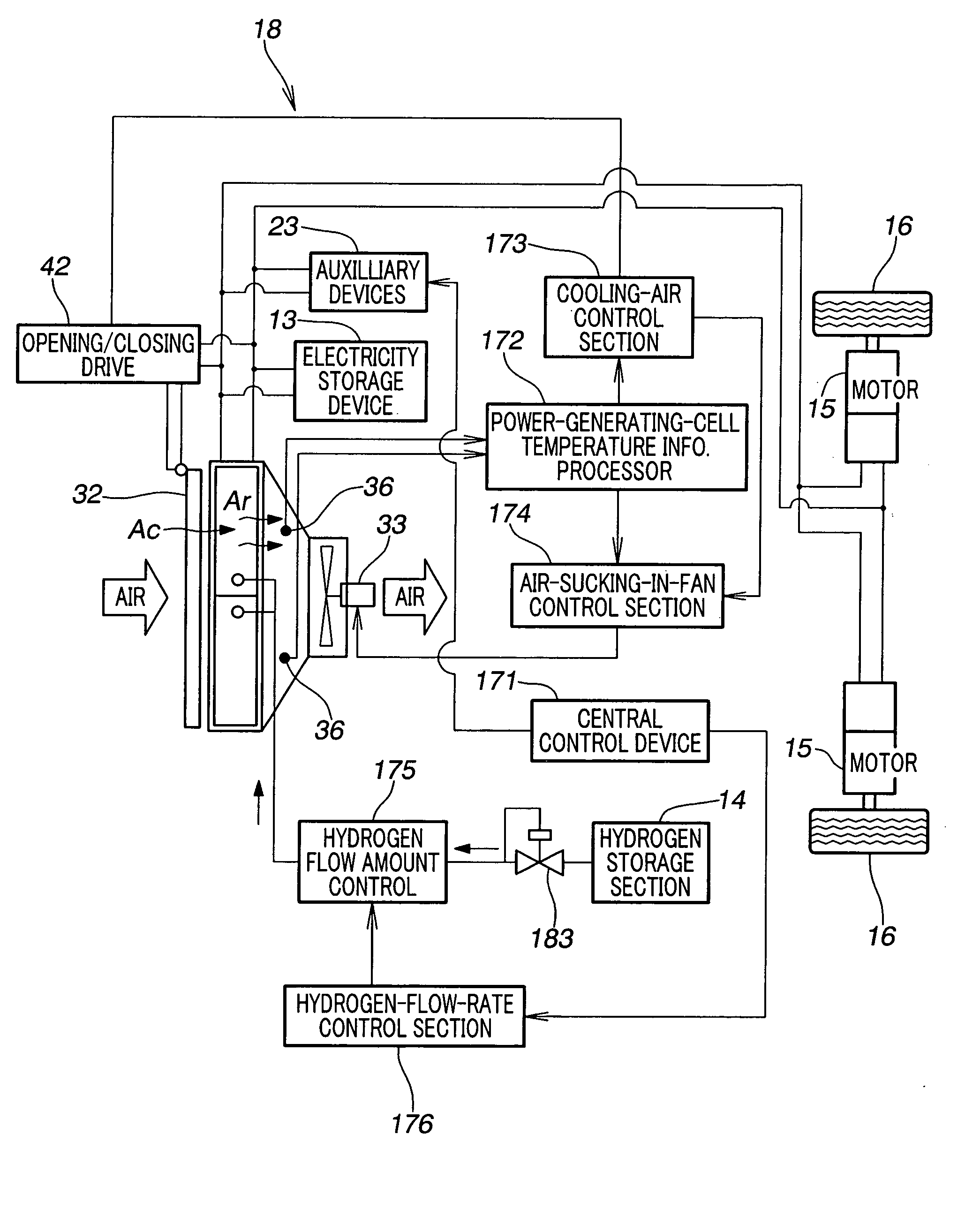
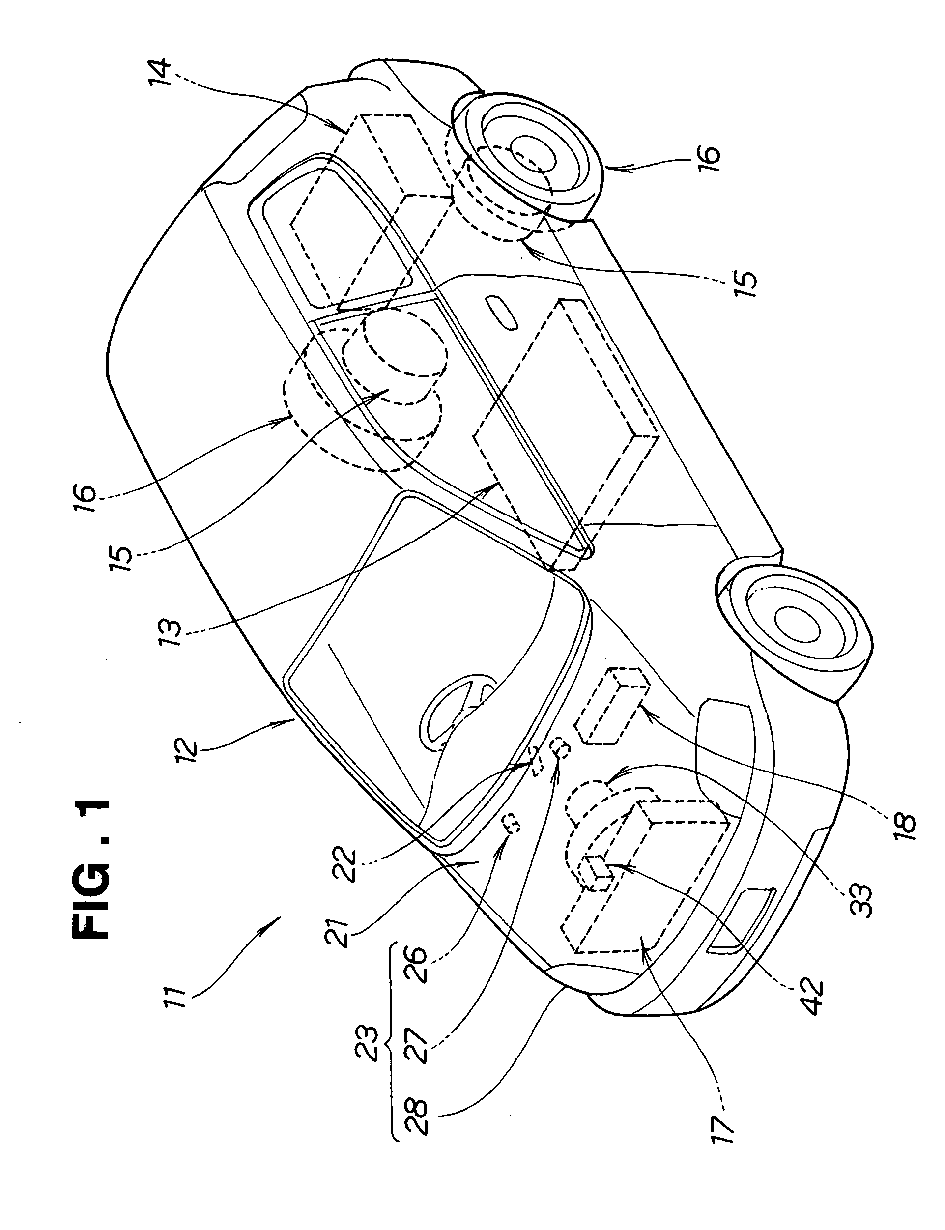
[0027]FIG. 1 is a perspective view of a vehicle employing a vehicle-mounted fuel cell stack controlled or operated in accordance with the present invention. The vehicle 11, which is a fuel-cell-powered vehicle running on hydrogen fuel, includes an electricity storage device 13 disposed centrally in a vehicle body 12, a hydrogen storage section 14 disposed in a rear portion of the vehicle body 12, traveling motors 15 disposed in rear portions of the vehicle body 12, and rear road wheels 16 coupled to the traveling motors 15. The vehicle 11 further includes a fuel cell stack 17 disposed in a front portion of the vehicle body 12, and a fuel cell control device 18 for controlling the vehicle-mounted fuel cell stack 17. In the figure, reference numeral 21 represents an engine room, 22 an accelerator pedal, and 23 auxiliary devices. The auxiliary devices 23 are electric devices other than the traveling motors 15, such as a wiper motor 26, air conditioner motor 27 and head lamps 28.

[0028]...


PUM

PropertyMeasurementUnit
temperatureaaaaaaaaaa
tmaaaaaaaaaa

Abstract

Temperature of power generating cells is measured, and, if the measured temperature is lower than a preset standard operating temperature, control is performed for zeroing an allocated amount of cooling air via an air allocation mechanism. During a startup period, cooling-air introduction openings are closed with reacting-air introduction openings kept open and an air-sucking-in fan activated. Thus, the entire amount of introduced air is caused to flow through the reacting-air introduction openings into the cells for reaction with hydrogen with a minimized cooling effect so that the power generation reaction can be promoted, which can reduce a time necessary for the cell temperature to increase up to a predetermined operating level. By constantly performing the control for zeroing the allocated amount of cooling air during the startup and subsequent periods, the power generating cell temperature is constantly allowed to rise readily as desired.

Description

FIELD OF THE INVENTION [0001] The present invention relates t0 an improved method for operating a vehicle-mounted fuel cell stack. BACKGROUND OF THE INVENTION [0002] Fuel-cell-powered vehicles known today use hydrogen as their fuel; specifically, these fuel-cell-powered vehicles are provided with a traveling motor and a fuel cell stack that generates electric power using hydrogen and oxygen, so that they can travel by electricity. One example of a conventional method for operating a fuel cell assembly is known from Japanese Patent Laid-Open Publication No. SHO-54-22537, and one example of a conventional method for operating a fuel cell unit mounted on an automotive vehicle is known from Japanese Patent Laid-Open Publication No. 2000-514745 (WO98 / 04013). [0003]FIG. 15 is a perspective view showing a fundamental construction and operation of the fuel cell assembly disclosed in the above-mentioned SHO-54-22537 publication. The disclosed fuel cell assembly includes fuel cell laminates 2...

Claims


Application Information

Patent Timeline
Patent Type & Authority Applications(United States)
IPC IPC(8): H01M8/10B60L11/18H01M8/04H01M8/24
CPCB60L11/1881B60L11/1892B60L11/1894H01M8/04014Y02E60/50H01M2008/1095H01M2250/20Y02T90/32Y02T90/34H01M8/04268B60L58/30B60L58/33B60L58/34Y02T90/40
Inventor OKAZAKI, KOJI
Owner HONDA MOTOR CO LTD
Why Eureka
Try Eureka