Measuring method and measuring device

a technology of measuring device and measurement method, which is applied in the field of fluorescent observation method, can solve the problem that the observation range ends up being limited to a very small part of the sample, and achieve the effect of preventing the saturation of fluorescent intensity

Inactive Publication Date: 2005-08-04
OLYMPUS CORP
View PDF10 Cites 30 Cited by
  • Summary
  • Abstract
  • Description
  • Claims
  • Application Information

AI Technical Summary

Benefits of technology

[0011] A fluorescence observation method according to a first aspect of the present invention comprises the steps of: arranging cells to be observed on a support; acquiring images of fluorescence emitted from the cells as a result of irradiating with excitation light at predetermined time intervals with a time-based image capturing system; and determining image capturing conditions such as the quantity of exposure light for capturing the fluorescent images to be subsequently acquired using the previously acquired fluorescent images to prevent saturation of fluorescent intensity.

Problems solved by technology

Thus, as the magnification of the objective lens increases, the observation range ends up being limited to a very small part of the sample.

Method used


Image

  • Measuring method and measuring device
  • Measuring method and measuring device
  • Measuring method and measuring device

Examples


first embodiment

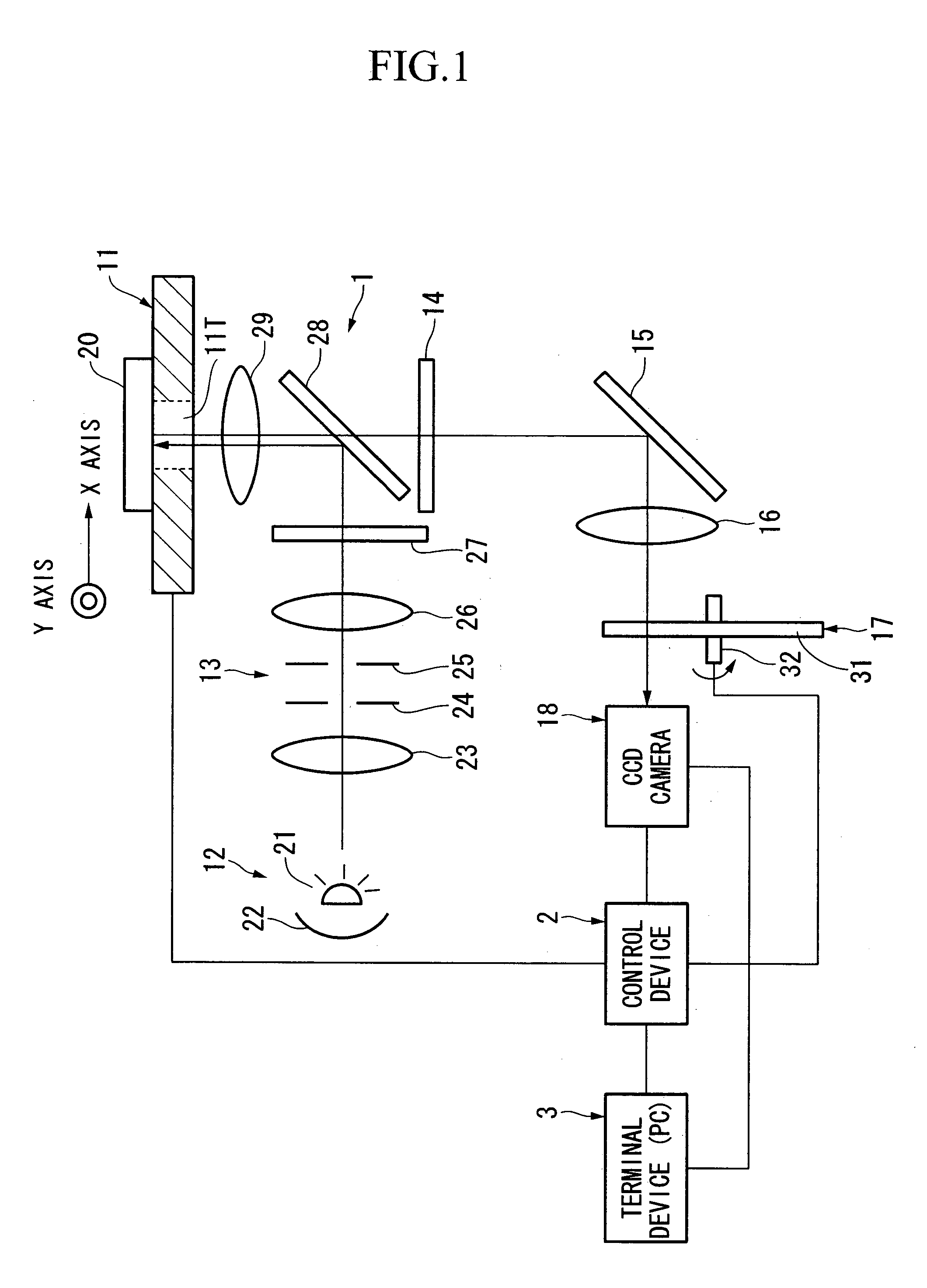
[0036] As shown in FIG. 1, a measuring device of the present invention includes a microscope 1, a control device 2 connected to the microscope 1, and a terminal device 3 connected to the control device 2.

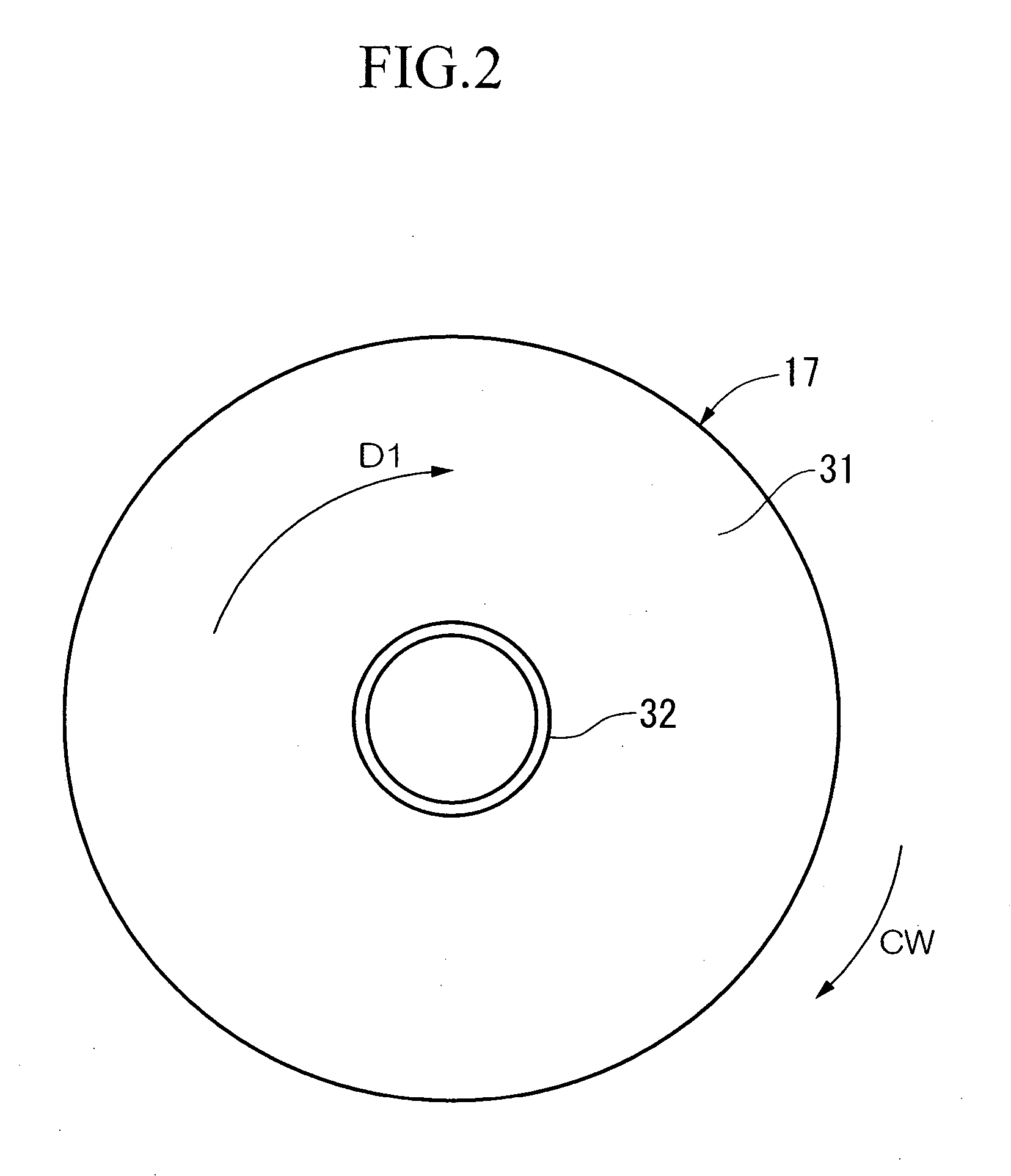
[0037] The microscope 1 has a motorized stage 11, a light source 12, an optical system 13 for fluorescent illumination, an excitation light cutoff filter 14, a mirror 15, an imaging lens 16, a motorized variable neutral density (ND) filter 17 and an image capturing system in the form of a solid-state image capturing unit 18 (hereinafter, to be referred to as a CCD (charge coupled device) camera). The constitution of microscope 1 and the number and arrangement of optical elements are not limited to the example shown in FIG. 1.

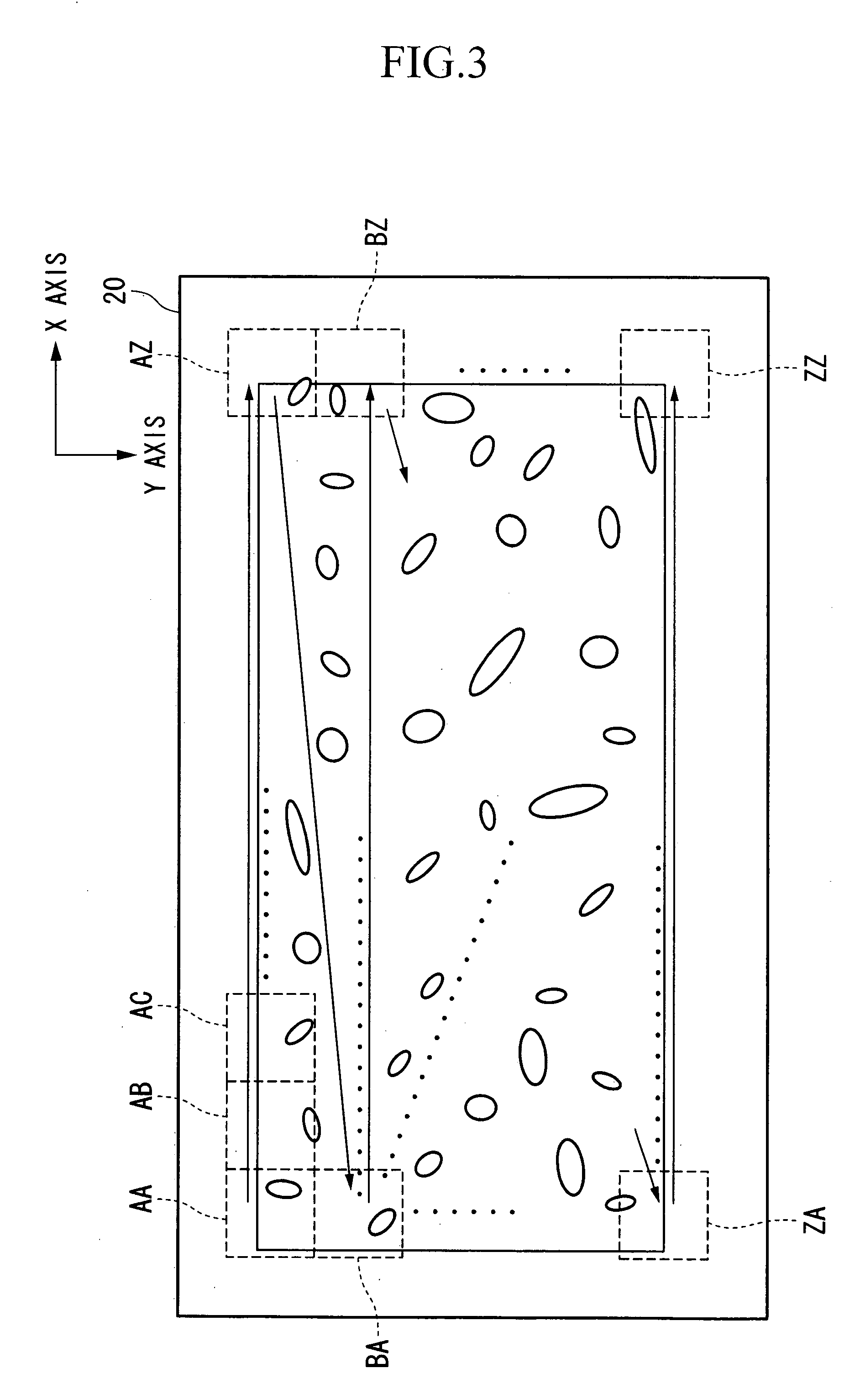
[0038] The motorized stage 11 holds a support 20 in a manner to allow two-dimensional scanning in the directions of the X axis and Y axis (perpendicular to the page) shown in the drawing. At least the portion of the motorized stage 11 on which the support 20 is...

third embodiment

[0086] Next, an explanation is provided of a measuring device according to the present invention with reference to FIG. 10. In the drawing, those constituents that are the same as those in each of the aforementioned embodiments are indicated with the same reference symbols, and their explanations are omitted to avoid repetition.

[0087] Although an area type CCD was used for the image capturing unit in the first and second embodiments, in this third embodiment, a line (or liner) CCD camera that uses a linear type of CCD is used for the image capturing unit. The quantity of the exposure light for image capturing is adjusted by controlling the video rate of the line CCD camera and the scanning speed of the motorized stage.

[0088] As shown in FIG. 10, line CCD camera 61 has sensors in the form of CCD 62 arranged in a row in the direction of the Y axis, and is fixed in coordinate plane XY In this measuring device, the control device 2 as shown in FIG. 1 moves the motorized stage 11 in the...

fourth embodiment

[0095] Next, an explanation is provided of a measuring device according to the present invention with reference to FIG. 1. In the drawing, those constituents that are the same as those in each of the aforementioned embodiments are indicated with the same reference symbols, and their explanations are omitted to avoid repetition.

[0096] The fourth embodiment uses a time delay integration (TDI) type of line (linear) CCD camera for the image capturing unit, and changes the quantity of the exposure light for the image capturing according to the number of stages of the TDI line of the TDI type of line CCD camera.

[0097] As shown in FIG. 11, a TDI type of line CCD camera 71 includes a shift register 72, TDI detector 73 and an amplifier (not shown). The TDI detector 73 has N number of stages (number of stages N=5 in FIG. 11) 74a through 74e. Each stage 74a through 74e has a plurality of columns 75a through 75j.

[0098] In the TDI type of the line CCD camera 71, an image obtained from a scanni...


PUM

PropertyMeasurementUnit
central excitation wavelengthaaaaaaaaaa
fluorescence observationaaaaaaaaaa
fluorescenceaaaaaaaaaa

Abstract

The measuring device according to the present invention has a support on which cells to be observed are arranged, an imaging lens that forms an image of reflected light reflected from the cells at an image capturing position as a result of being irradiated with excitation light, and a photoelectric conversion sensor arranged at the image capturing position that converts the formed images of reflected light into images of the cells. The images of the cells captured according to first optical image capturing conditions are analyzed, second optical image forming conditions are determined corresponding to the results of that analysis, and subsequent images of the cells are captured when a predetermined amount of time has elapsed according to the second optical image capturing conditions.

Description

BACKGROUND OF THE INVENTION [0001] 1. Field of the Invention [0002] The present application claims priority on Japanese Patent Application No. 2004-25389 filed on Feb. 2, 2004, the content of which is incorporated herein by reference. [0003] The present invention relates to a fluorescence observation method for observing the fluorescence of cells and a measuring device for measuring the fluorescence of cells. [0004] 2. Description of the Related Art [0005] Accompanying recent progress in the field of gene technology, the gene sequences of numerous organisms, including humans, have been identified. The causative relationships between gene products, such as analyzed proteins, and diseases are beginning to be elucidated, accordingly. In addition, attempts are being made to analyze various proteins and genes both comprehensively and statistically by carrying out various tests using cells. In order to carry out such tests, it is necessary to acquire predetermined information while cultur...

Claims


Application Information

Patent Timeline
Patent Type & Authority Applications(United States)
IPC IPC(8): C12M1/34C12Q1/00C12Q1/68G01N21/64G01N33/48G01N33/483G02B21/36G06K9/00
CPCG01N21/6452G01N21/6486G01N21/6458
Inventor SHIMAMOTO, ATSUYOSHI
Owner OLYMPUS CORP
Why Eureka
Try Eureka