Dual well port device

a well port and well technology, applied in the direction of catheters, other medical devices, medical preparations, etc., can solve the problems of inability to eject fluid through the same lumen, require special handling, and are dangerous to insert and remove catheters

Active Publication Date: 2005-08-04
ANGIODYNAMICS INC
View PDF30 Cites 106 Cited by
  • Summary
  • Abstract
  • Description
  • Claims
  • Application Information

AI Technical Summary

Problems solved by technology

It is impractical and dangerous to insert and remove the catheter for each session.
For example, certain chemotherapy agents are incompatible with one another and, therefore, require special handling during therapeutic sessions.
Some of these fluids cannot be infused through the same lumen because they may coagulate or form a precipitate that clogs the port or catheter lumen.
In other instances, the fluids may be incompatible for other reasons, and are therefore kept separate until they reach the patient's blood stream.
Providing two unmixable therapeutic fluids to a dual lumen catheter or to two separate catheters near each other presents challenges, since a conventional port cannot be used to inject both fluids.
Ports are generally not implanted near one another because of the surgery required to insert each port in place, and the additional complications that may arise as a result of the port residing in an area.
However, conventional dual well port devices are larger than single port devices, and may be difficult to place in the patient's body.

Method used


Image

  • Dual well port device
  • Dual well port device
  • Dual well port device

Examples


Embodiment Construction

[0015] The present invention may be further understood with reference to the following description and the appended drawings, wherein like elements are referred to with the same reference numerals. The present invention is related to medical devices that are used to access the vascular system of a patient. In particular, the present invention relates to access ports used to inject therapeutic agents into the patient vasculature.

[0016] Semi-permanently placed ports may be useful for a variety of medical procedures which require repeated access to a patient's vascular system. For example, chemotherapy infusions may be repeated several times a week for extended periods of time. For safety reasons, as well as to improve the comfort of the patient, injections of these therapeutic agents may be better carried out with an implantable, semi-permanent vascular access port. There are many conditions that require chronic venous supply of therapeutic agents, nutrients, antibiotics, blood produ...


PUM


Abstract

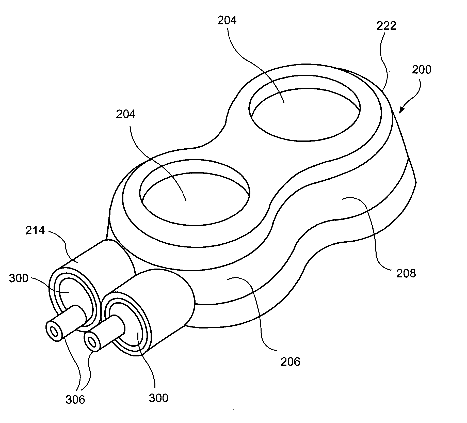
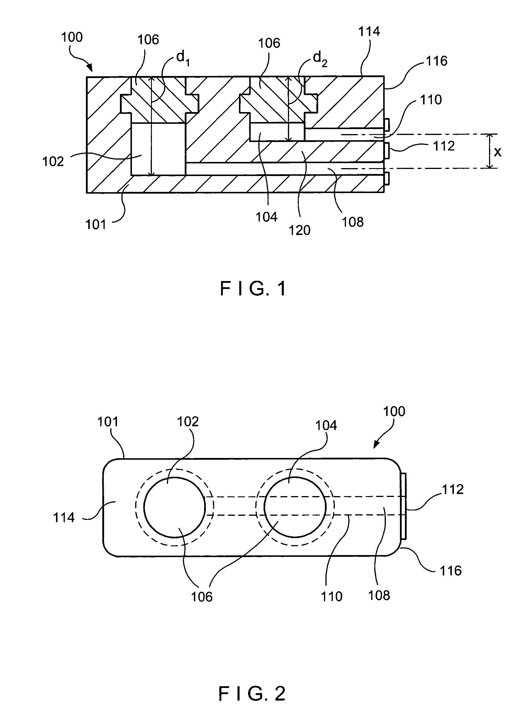
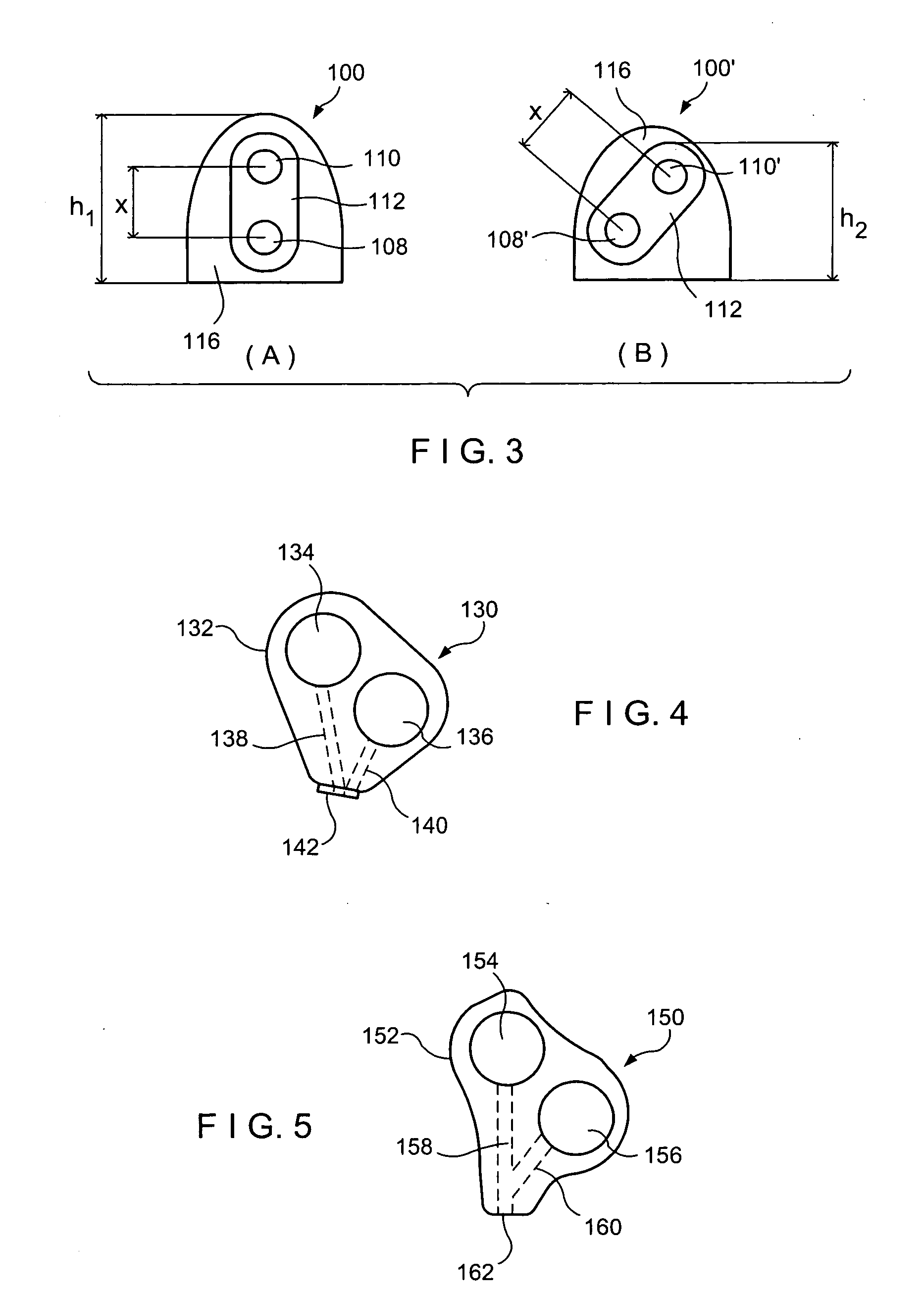
A port for implantation within a body, comprises a housing having a proximal surface, a distal surface and a side surface wherein, when the port is implanted within a body in a desired orientation, the proximal surface faces outward toward the skin, the distal surface faces inward away from the skin and the side surface extends between the proximal and distal surfaces and a first well formed within the housing, the first well including a first opening in the proximal surface. A second well is formed in the housing adjacent to the first well and has a second opening formed in the proximal surface. First and second outlet openings formed on the side surface of the port are in fluid communication with the first and second wells, respectively, and are separated from one another by a distance substantially equal to a distance separating lumens of a dual lumen catheter to which the port is to be connected. In addition, a method of infusing fluids to a patient, comprises attaching a dual lumen catheter to a blood vessel of the patient and implanting subcutaneously a port including first and second openings separated by a distance substantially equal to a distance between the dual lumens of the catheter, wherein the first opening is in fluid communication with a first well of the port and the second opening is in fluid communication with a second well of the port. The dual lumen catheter is then connected to the first and second openings of the port and a first fluid is provided to the first well while a second fluid is provided to the second well.

Description

[0001] The present application incorporates by reference the entire disclosure of U.S. application entitled “Pressure Activated Safety Valve With Anti-Adherent Coating” filed on even day herewith naming Karla Weaver and Paul DiCarlo as inventors, U.S. application entitled “Stacked Membrane For Pressure Actuated Valve” filed on even day herewith naming Karla Weaver and Paul DiCarlo as inventors, U.S. application entitled “Pressure Activated Safety Valve With High Flow Slit” filed on even day herewith naming Karla Weaver and Paul DiCarlo as inventors, and U.S. application entitled “Pressure Actuated Safety Valve with Spiral Flow Membrane” filed on an even day herewith naming Paul DiCarlo and Karla Weaver as inventors. BACKGROUND OF THE INVENTION [0002] Many medical procedures require repeated and prolonged access to a patient's vascular system. For example, chemotherapy, paraternal nutrition antibiotic regimens, blood withdrawals and other similar treatments require such repeated acce...

Claims


Application Information

Patent Timeline
Patent Type & Authority Applications(United States)
IPC IPC(8): A61M25/00A61M39/02A61M39/24
CPCA61M39/0208A61M2039/0211A61M39/24
Inventor DALY, KATIEDIMATTEO, KRISTIANHOUDE, ERIC
Owner ANGIODYNAMICS INC
Why Eureka
Try Eureka