
Methods and systems for large-scale airframe assembly

Active Publication Date: 2005-08-11
THE BOEING CO
View PDF32 Cites 119 Cited by
  • Summary
  • Abstract
  • Description
  • Claims
  • Application Information

AI Technical Summary

Benefits of technology

[0005] The present invention is directed to methods and systems for performing position measurements during large-scale airframe assembly. Embodiments of methods and systems in accordance with the invention may advantageously provide measurements during various stages of the large-scale airframe assembly process in a non-intrusive, economical manner, and may improve the overall accuracy and efficiency of the assembly process.

Problems solved by technology

The holding tools support the aircraft components and provide limited movement capability to slide components together.
For example, large components may deviate from their nominal design due to their complexity and non-uniform material properties.
These abnormalities may slightly reduce fuel efficiency and may increase manufacturing flow time if trim needs to be corrected.
In addition, in many assembly situations measurement technologies are not available to verify that the above-noted assumptions are correct as early in the assembly process as desirable to make needed corrections.
Existing measurement technologies are often too expensive or overly intrusive to the assembly process to adequately address this issue.
Furthermore, because of the cost and unique design of each holding tool, changes to the aircraft that require tool modifications are typically quite expensive and time consuming.

Method used


Image

  • Methods and systems for large-scale airframe assembly
  • Methods and systems for large-scale airframe assembly
  • Methods and systems for large-scale airframe assembly

Examples


Embodiment Construction

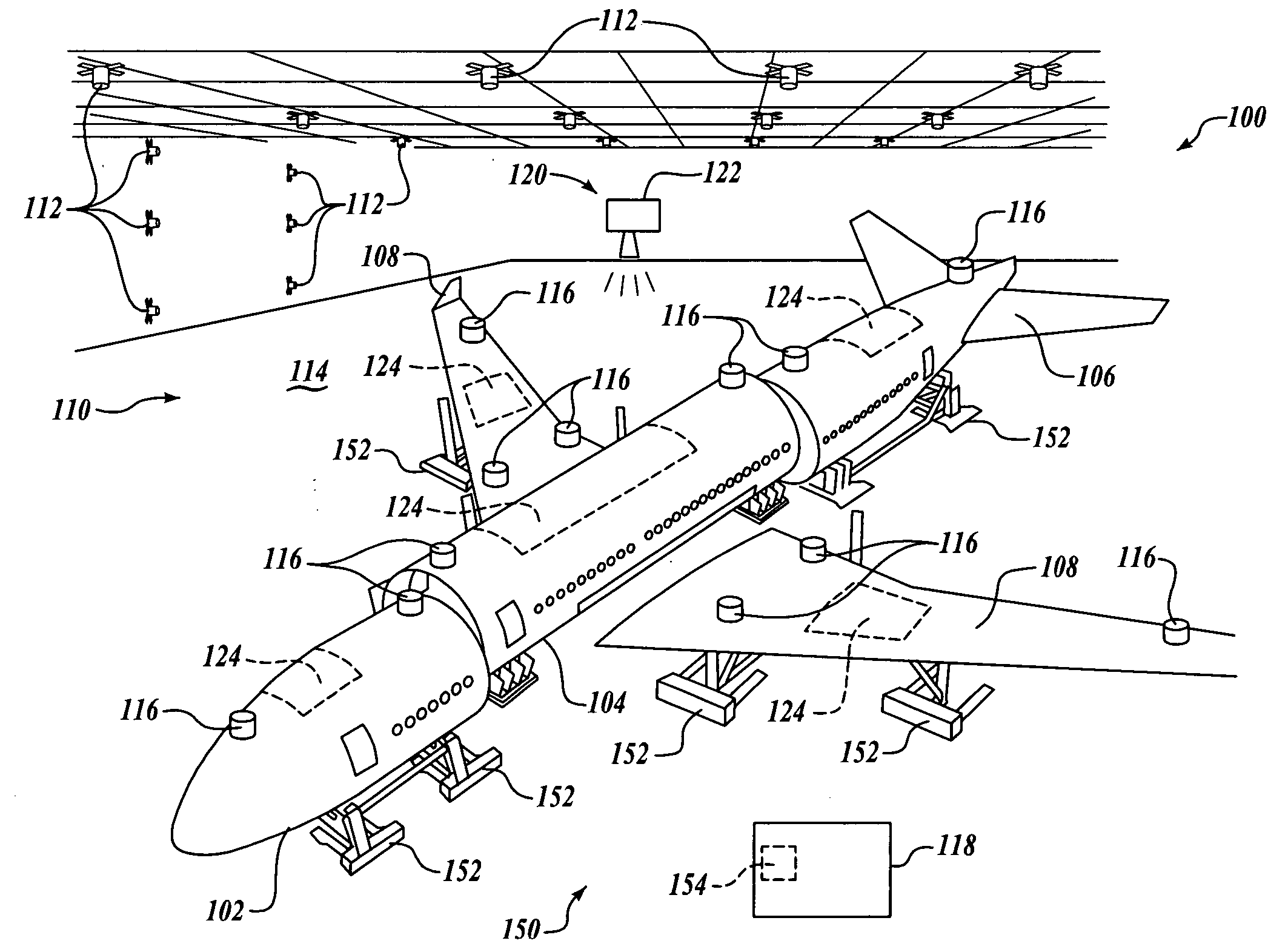
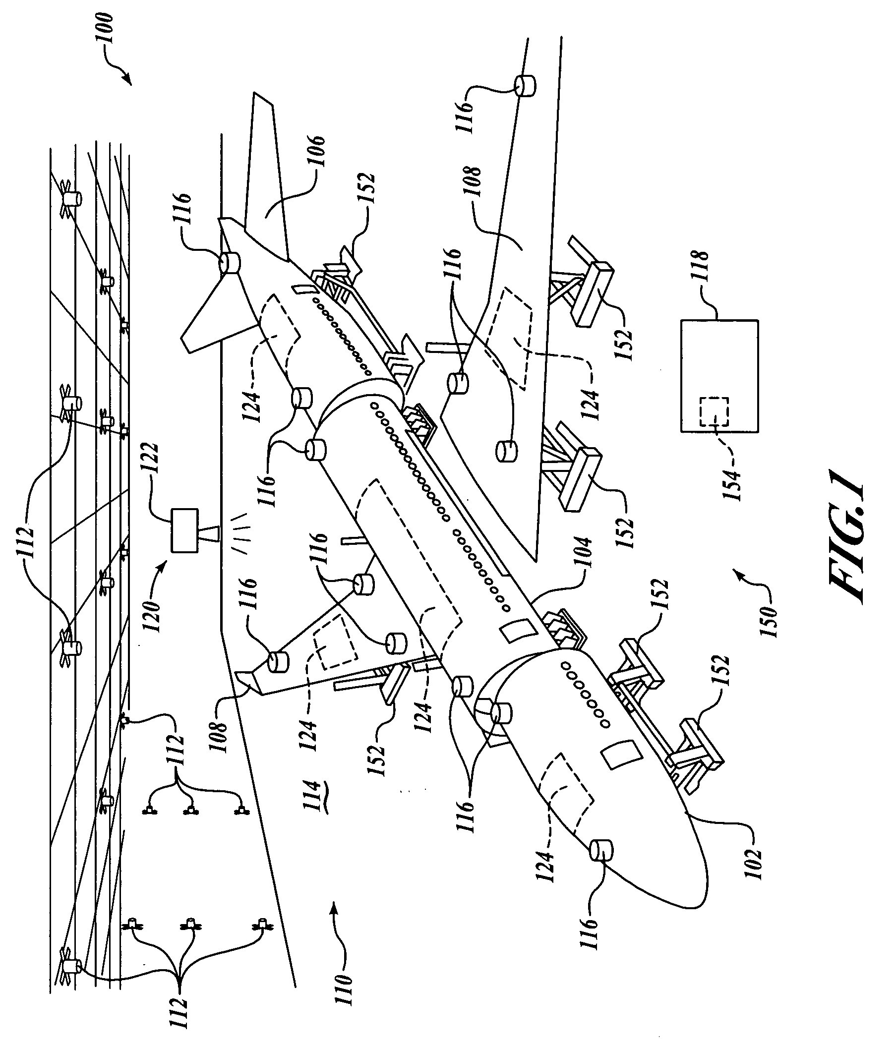
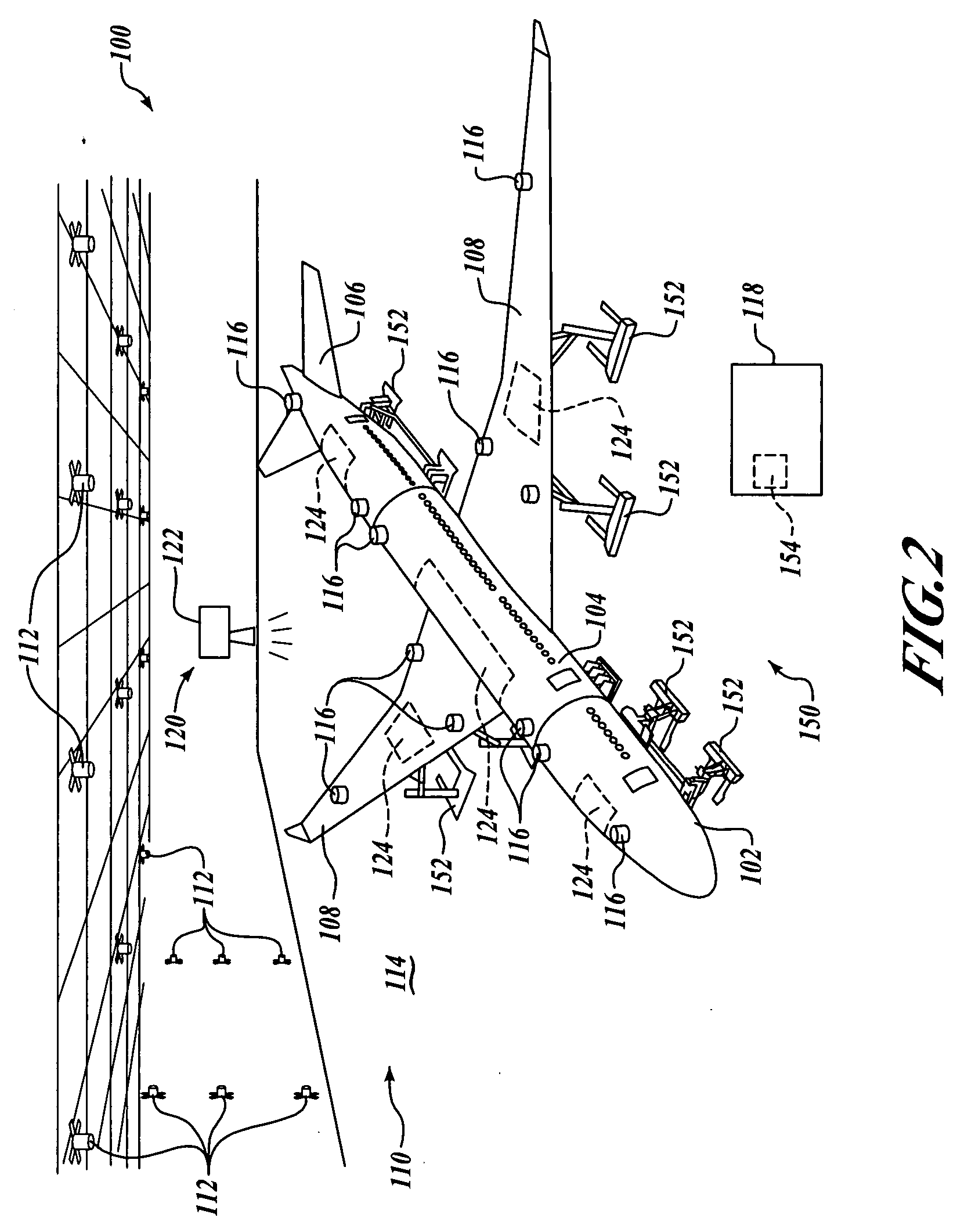
[0011] The present invention relates to methods and systems for performing position measurements during aircraft assembly, including large-scale airframe assembly. Many specific details of certain embodiments of the invention are set forth in the following description and in FIGS. 1-3 to provide a thorough understanding of such embodiments. One skilled in the art, however, will understand that the present invention may have additional embodiments, particularly combinations of discrete and surface measurements, and that the present invention may be practiced without several of the details described in the following description.

[0012] Generally speaking, embodiments of methods and systems in accordance with the present invention may advantageously reduce or eliminate the need for large, fixed holding tools during the assembly of various components of large structures, including the assembly of large aircraft. In one embodiment, an assembly process of a large structure includes measur...


PUM


Abstract

Methods and systems for large-scale airframe assembly are disclosed. In one embodiment, a method includes measuring a plurality of discrete point positions at least one of on and adjacent to at least one of a first and a second component, and measuring at least one surface position on the at least one of the first and second components. The measured positions are compared with a desired position information (e.g., a computer aided design model). The comparison may include applying a fitting routine to the measured positions and the desired position information. Next, a transformation matrix for improving the comparison between the measured positions and the desired position information is computed. At least one of the first and second components is then moved according to the transformation matrix. During movement, the plurality of discrete point positions may be monitored and provided to the position control system by a feedback loop.

Description

FIELD OF THE INVENTION [0001] The present disclosure relates to methods and systems for performing position measurements during large-scale airframe assembly, and more specifically, to methods and systems for performing position measurements utilizing integrated discrete positioning and surface mapping systems. BACKGROUND OF THE INVENTION [0002] Aircraft components are currently assembled in large holding tools or fixtures. Such tools are substantially rigid and are usually fixed to a factory floor. The holding tools support the aircraft components and provide limited movement capability to slide components together. In large-scale airframe assembly, it is typically assumed that if the holding tool is in the correct position, then the point on the aircraft component where the tool touches or supports the aircraft component will be known, and hence all coordinates on the component are known, and thus, the airframe assembly is correct and the aircraft will meet its aerodynamic require...

Claims


Application Information

Patent Timeline
IPC IPC(8): G05B19/418
CPCG05B19/41805G05B2219/31068G05B2219/45055Y10T29/49829Y10T29/53061Y10T29/49778Y10T29/4978B64F5/10Y02P90/02
Inventor COBB, JAMES M.NIELSEN, TIMOTHY G.PALMATEER, JOHN W.DELAND, JAMES A.
Owner THE BOEING CO
Learn More