Additive dispensing filter apparatus

a filter apparatus and additive technology, applied in the direction of filter cartridges, filtration separation, separation processes, etc., can solve the problems of high and very cost-intensive design complexity to achieve effective addition of additive to liquid circulation, inability to release additive, and inability to completely know the effect of oil circulation effect, etc., to achieve the effect of reducing temperature, reducing the decomposition rate, and increasing the release of additiv

Inactive Publication Date: 2005-08-11
MANN HUMMEL GMBH
View PDF6 Cites 75 Cited by
  • Summary
  • Abstract
  • Description
  • Claims
  • Application Information

AI Technical Summary

Benefits of technology

[0039] According to an advantageous embodiment of this method, the rate of decomposition is controlled by partial encapsulation of the additive. In this way the area of the additive coming in contact with the liquid can be influenced in such a way as to control the release of additive preferably over the entire duration of the filtration interval.
[0040] Alternatively, the method may be influenced in such a way that the decomposition rate is controlled by the positioning of the additive in areas having a suitable flow rate. The decomposition rate is easily influenced by increasing or reducing the flow rates. Thus on the basis of the flow rates in the interior of the housing, known from experiments, it is possible through the positioning of the additive to adjust the decomposition rate to the filtration interval until changing of the filter element.
[0041] Another possibility for controlling the decomposition rate is to perform a warming by means of a heating and / or cooling element in the area of the additive configuration, depending on the desired rate of release of the additive. For example, a sensor here may measure the liquid quality and influence the warming of the heating or cooling element via control signals such that a permanently uniform liquid quality is adjustable. For this case, an increase in temperature in the area of the additive configuration causes an increased release of additive, and a reduction in temperature causes a reduced rate of release additive.
[0042] It is likewise possible to control the rate of decomposition by varying the effective liquid wetting area of the additive over the duration of the changing interval. This may be accomplished, for example, by way of a dissolving membrane placed over the additive or by a special arrangement of the additive in the housing. For example, if the additive is introduced into a conically shaped housing section of the housing, then the effective liquid wetting area of the additive is also reduced over the course of decomposition due to the reduced diameter of the cone.
[0043] According to an alternative embodiment of the method, the additive is arranged in the housing in encapsulated form, with openings being provided in the encapsulation, the openings being variable such that all opening diameters between zero and full opening are achievable. This may be accomplished, e.g., by direct motor drive or via a kinematic coupling of these openings. In addition, a sensor is provided in the liquid circuit to measure the liquid quality and at least one of these measured results leads to an adjustment in the opening size of the openings of the additive container. In this way it is possible to actively and directly regulate the additive release rate as a function of the prevailing liquid quality.

Problems solved by technology

One disadvantage of these approaches is that the additive is not released until a sheathing or covering part has been dissolved or inert vehicle substances such as polymers are used or foreign substances such as PTFE are added.
One problem here is that substances whose effects on the oil circulation are not absolutely known are being added to the oil circulation.
One disadvantage here is the high and very cost-intensive design complexity to achieve effective addition of an additive to the liquid circulation.

Method used


Image

  • Additive dispensing filter apparatus
  • Additive dispensing filter apparatus
  • Additive dispensing filter apparatus

Examples


Embodiment Construction

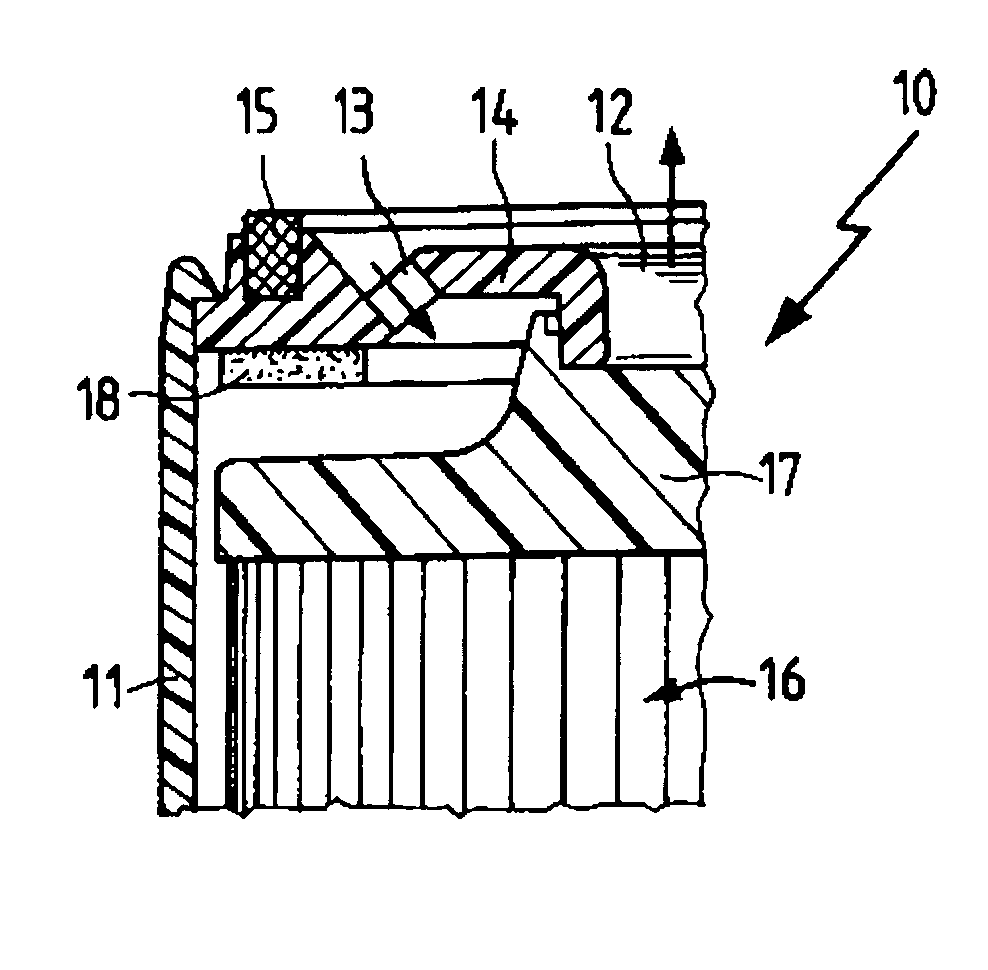
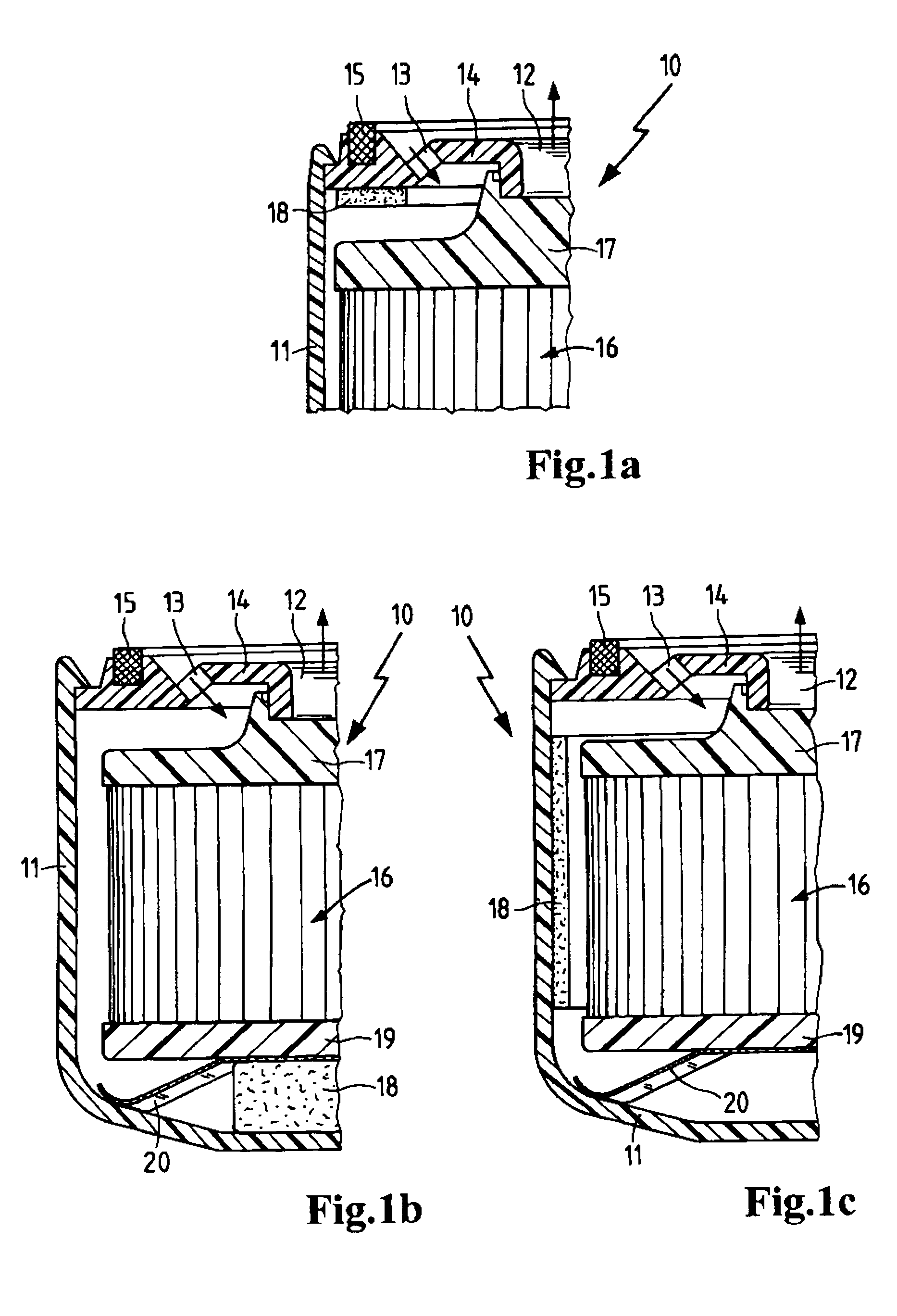
[0050]FIGS. 1a, b and c show an inventive replaceable filter in a sectional view. FIG la shows a part of the filter device 10 with a housing 11, whereby an outlet 12 and an inlet 13 are arranged in a housing cover 14 which is undetachably joined to the housing 11. The housing cover 14 has a peripheral quadrilateral gasket 15 which ensures an axial sealing of the filter device 10 in cooperation with a connecting flange (not shown here). The inlet 13 and the outlet 12 are separated by a filter medium 16 with an end disk 17 mounted at the top end. The filter medium 16 is a hollow cylindrical paper filter element with stellate pleating. The end disk 17 ensures the separation of the crude side from the clean side in the upper area, providing a seal radially and axially. In the lower area of the housing 14, an additive 18 is arranged circumferentially in the form of a ring; because of its gelatinous substance, it has both dimensional stability and elasticity and is glued to the housing co...


PUM

PropertyMeasurementUnit
permeableaaaaaaaaaa
cylindrical shapeaaaaaaaaaa
diameteraaaaaaaaaa

Abstract

An apparatus for filtering a liquid, with a housing, a liquid inlet arranged in the housing, a liquid outlet arranged in the housing, a filter for removing particles from a liquid stream arranged between the liquid inlet and the liquid outlet, and at least one additive for functionally altering the liquid properties arranged in the apparatus, in which the additive is arranged in the interior volume of the apparatus and is shaped in a colloidally disperse, dimensionally stable, elastic form corresponding to at least one geometric space defined by an interior structure of the apparatus or of the filter for removing the particles.

Description

BACKGROUND OF THE INVENTION [0001] This invention relates to an additive dispensing filter apparatus and to a method for dispensing an additive to a liquid. [0002] It is known that operating liquids can be conditioned through filters so that the liquid system is protected from wear and damage. This is accomplished by removing particles, in particular particles that are relevant for wear, from the liquid system by filtration. It is also known that special chemical substances may be added to a filter for continuous oil care. In contact with the liquid to be filtered, the chemical substances (additives) are dissolved and in doing so release their active ingredients. These active ingredients fulfill the following functions: they protect the oil from thickening, from an increase in viscosity due to oxidation; they improve the lubricant properties of moving parts, dissolving deposits, dispersing foreign substances, providing protection against wear and improved flow properties. These addi...

Claims


Application Information

Patent Timeline
Patent Type & Authority Applications(United States)
IPC IPC(8): B01D27/06B01D37/02
CPCB01D27/06B01D37/025B01D2201/02Y10S210/17B01D2201/298B01D2201/0415B01D27/144
Inventor KLEIN, GUNNAR-MARCELKOLCZYK, MARKUSJOKSCHAS, GUENTERHARENBROCK, MICHAELKRAMER, JOERG
Owner MANN HUMMEL GMBH
Why Eureka
Try Eureka