Fluid dispenser

a dispenser and fluid technology, applied in the field of fluid dispensers, can solve the problems of slowing down or stopping the growth of germs in the fluid, and achieve the effect of preventing the formation

Active Publication Date: 2005-08-11
URSAPHARM ARZNEIMITTEL
View PDF5 Cites 26 Cited by
  • Summary
  • Abstract
  • Description
  • Claims
  • Application Information

AI Technical Summary

Benefits of technology

[0004] One aspect of the present invention provides a fluid dispenser of the kind as referred to in DE 40 27 320 C2 which does not cause compatibility problems and p

Problems solved by technology

For example, the interaction could result in a slowing d

Method used


Image

  • Fluid dispenser
  • Fluid dispenser

Examples


Embodiment Construction

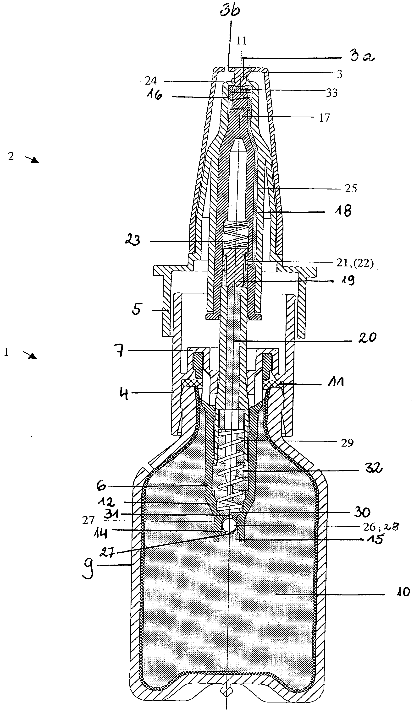
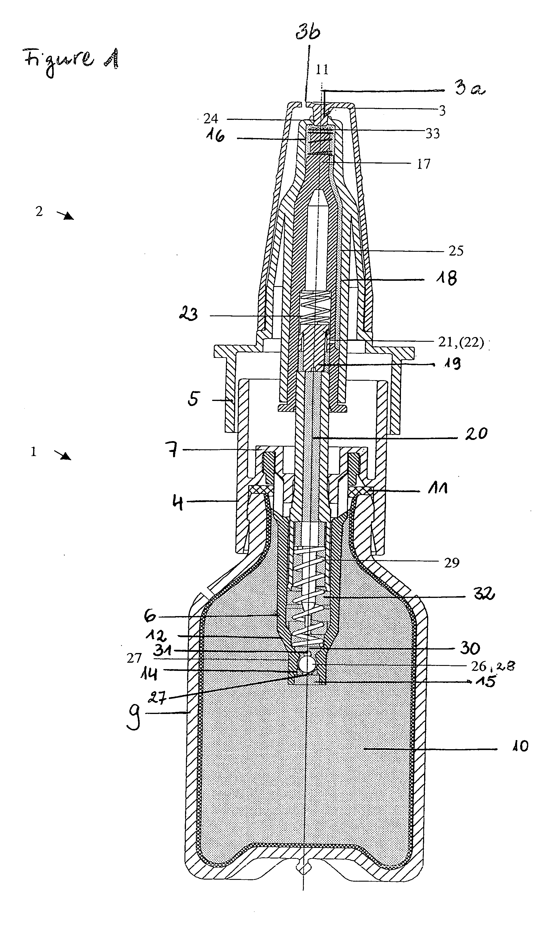
[0015] As shown in the FIGURE, the device comprises a metering pump consisting of a cylindrical pump body 1, an operating plunger 2 and a cap 3.

[0016] The pump body 1 comprises a first hollow cylindrical body part 4, shown in the drawing as open at the bottom, a second hollow cylindrical body part 5 of bigger diameter (part 5 is part of the operating plunger 2), open at the top in the drawing, and a hollow cylinder 6 that is open at both ends and is fixed centrally on an inwardly directed annular flange 7 in the transition region between the two parts 4,5 of the pump body. The first body part 4 may have an internal screw thread into which a container 9 filled with a germ-free fluid and indicated only generally, can be screwed. As an alternative, instead of the internal screw thread, a snap on closure can be used as shown in the FIGURE. A seal 11 is provided on the underside (in the drawing) of the annular flange 7 to ensure an air-tight seal between the container 9 and the pump bod...


PUM


Abstract

A fluid dispenser for germ-free fluid is described incorporating at least one material being capable of interacting via an oligodynamically active substance. The dispenser includes a metering pump and inlet and outlet valves. The fluid coming into contact with at least one oligodynamically active substance is present in the region of the outlet valve, of the inlet thereto and/or the outlet therefrom.

Description

TECHNICAL FIELD OF THE INVENTION [0001] The invention relates to a fluid dispenser for germ-free fluids. DESCRIPTION OF RELATED ART [0002] In the Pharmazeutische Zeitung, 124, No. 20, of May 17, 1979, on pages 949 and 950, a fluid dispenser is described that has the form of a dropping pipette and is attached to a container containing eye-drops. Inside the dropping pipette a silver deposit consisting of a layer of silver or a difficultly-soluble silver salt is disposed so that airborne germs drawn in with the drops that run back into the container have to pass an antimicrobial (oligodynamical) active silver layer before they enter the container. It is also stated that ceramic rings with silver chloride embedded and having a diameter of 9 mm have been found to be suitable. These ceramic rings can be firmly installed in the droppers of all the usual kinds of pharmaceuticals, eye-dropper bottles simply by pushing them in. This method of introducing the silver deposit into the droppers h...

Claims


Application Information

Patent Timeline
IPC IPC(8): B05B11/00B67D7/76
CPCB05B11/0032B05B11/3042B05B11/0043B05B11/026B05B11/1042
Inventor BUXMANN, DETMAR
Owner URSAPHARM ARZNEIMITTEL
Why Eureka
Try Eureka