
Detector for variable pressure areas and an electron microscope comprising a corresponding detector

a detector and variable pressure technology, applied in the field of interaction products detectors, can solve the problems of inconvenient use of detectors with varying gas pressures in the region, detectors that cannot be used with high pressure in the sample chamber, and disturbance of scintillators

Inactive Publication Date: 2005-08-11
CARL ZEISS SMT GMBH
View PDF6 Cites 47 Cited by
  • Summary
  • Abstract
  • Description
  • Claims
  • Application Information

AI Technical Summary

Benefits of technology

[0012] The object of the present invention is therefore to provide a detector that can be used both under high vacuum conditions and also at high pressures in the sample chamber of an electron microscope.
[0019] In a further advantageous embodiment, the detector has a light guide. The light guide can itself consist of scintillator material. Such a light guide serves to efficiently conduct photons produced in the scintillator to the photodetector.

Problems solved by technology

Such Everard-Thornley detectors cannot be used with varying gas pressures in the region of the detector, particularly when the ambient pressure of the detector is above 10−3 hPa, since the increased conductivity of the residual gas leads to overstrikes at the high voltage applied to the scintillator.
In this detector it is however disadvantageous that the scintillator has to be arranged between the sample and the objective lens of the scanning electron microscope, so that a correspondingly greater working distance is necessary between the objective lens and the sample; because of the resulting scattering of the electrons by gas molecules, this detector is unsuitable for uses with high pressures in the sample chamber.
Moreover, the scintillator is disturbed by a tilting of the sample.

Method used


Image

  • Detector for variable pressure areas and an electron microscope comprising a corresponding detector
  • Detector for variable pressure areas and an electron microscope comprising a corresponding detector
  • Detector for variable pressure areas and an electron microscope comprising a corresponding detector

Examples


Embodiment Construction

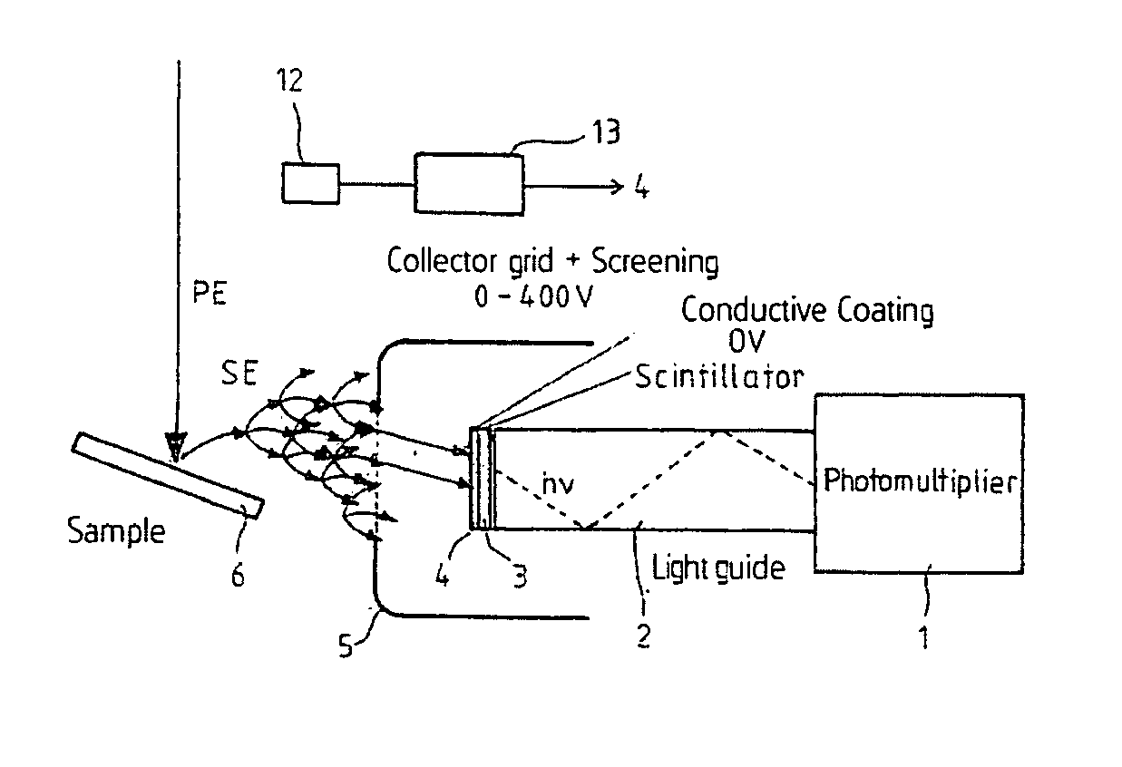
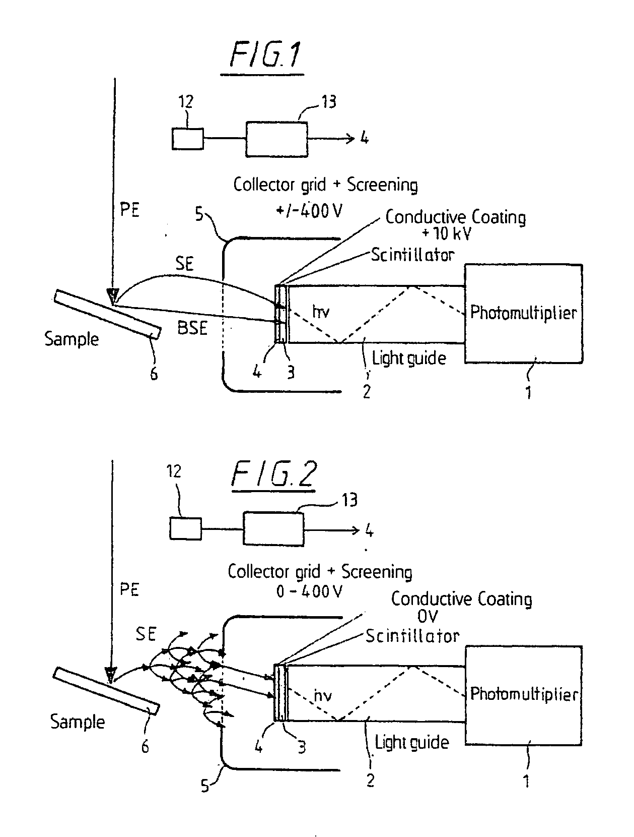
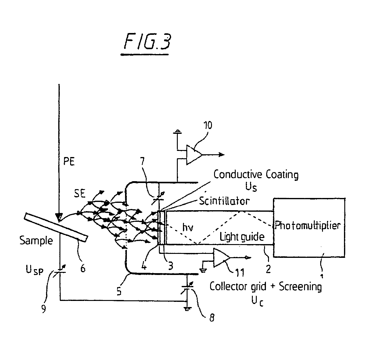
[0027] The detector in FIG. 1 contains a photodetector (1), for example in the form of a photomultiplier or an avalanche photodiode, and a light guide (2) connected before the photodetector (1), and a scintillator (3) connected to the end face of the light guide (2) remote from the photodetector (1).

[0028] It should be mentioned here that the light guide (2) is not absolutely necessary, but the scintillator can instead be installed directly before the photodetector (1). In this case the photodetector (1) of course has to be arranged within the specimen chamber of the electron microscope, while with the light guide (2), the photodetector can be arranged outside the specimen chamber, since light produced within the specimen chamber is guided by the light guide (2) to the photodetector (1).

[0029] Furthermore, it should be mentioned here that the light guide (2) itself can also be constructed as a scintillator, so that a separate scintillator layer (3) can be dispensed with.

[0030] Th...


PUM


Abstract

A detector for scanning electron microscopes, which can be used under different pressure conditions in the specimen chamber of the electron microscope, designed for the detection of both electrons and light. For this purpose, the detector has a photodetector and a scintillator of a material transmissive for visible light connected before the photodetector. The scintillator can be provided with a coating transparent to visible light. By the application of different potentials, the detector is suitable for the detection of electrons in high vacuum and for the detection of light with high pressures in the specimen chamber.

Description

CROSS-REFERENCES TO RELATED APPLICATIONS [0001] This is a Continuation application of PCT / EP01 / 07431 claiming priority of German Patent Applications 100 32 599.8 filed Jul. 7, 2000 and 101 26 698.7 filed May 31, 2001.[0002] Not applicable. STATEMENT REGARDING FEDERALLY SPONSORED RESEARCH OR DEVELOPMENT [0003] Not applicable. BACKGROUND OF THE INVENTION [0004] The invention relates to a detector for the interaction products, particularly backscattered electrons and secondary electrons, produced in a particle beam device by interaction of a primary beam with a sample to be investigated. [0005] Usually used for the detection of secondary electrons or backscattered electrons in scanning electron microscopes are so-called Everard-Thornley detectors (ETD), in which the secondary electrons or backscattered electrons released at the sample interface are attracted away from the sample to the detector by an extraction grid and then accelerated to a scintillator having a high voltage of about ...

Claims


Application Information

Patent Timeline
Patent Type & Authority Applications(United States)
IPC IPC(8): H01J37/18H01J37/244H01J37/28
CPCH01J37/244
Inventor GNAUCK, PETERDREXEL, VOLKERESSERS, ERIK
Owner CARL ZEISS SMT GMBH
Learn More