Duplex printing system

a printing system and duplex technology, applied in the direction of digital output to print units, electrographic processes, instruments, etc., can solve the problem of large deviation of the image position of the front side, and achieve the effect of stable precision

Inactive Publication Date: 2005-08-11
RICOH KK
View PDF16 Cites 34 Cited by
  • Summary
  • Abstract
  • Description
  • Claims
  • Application Information

AI Technical Summary

Benefits of technology

[0007] It is an object of the invention to provide a duplex printing system capable of implementing control of aligning print positions on both sides even when an alignment mark cannot be formed in a fixed position.
[0008] According to one aspect of the invention, there is provided with a duplex printing system including: a first printer for forming an image on a first side of a web without a feed hole; a second printer which is provided in a backward stage of the first printer and forms an image on a second side of the web; a control device for transporting print data and a web transport signal indicating instruction of printing to the first printer and the second printer; mark detection means for detecting an alignment mark formed on the web; and image alignment control means for matching a position of the image formed on the second side with a position of the image formed on the first side of the web by controlling a transport speed of the web so as to match a phase of the web transport signal with a phase of a mark detection signal from the mark detection means By thus configuration, a printing system can accurately print an image on a second side in a state being matched with an image of a first side with stable precision even in the case of using a web in which some marks are previously printed or in the case of having to print a mark etc. used in control of a device for cutting a print result.

Problems solved by technology

At this time, when there is another mark as described above in a formation portion of the alignment mark, it is likely that due to wrong detection of the alignment mark, the image position of the front side largely deviates from the image position of the back side or trouble occurs in control of the cutting device.

Method used


Image

  • Duplex printing system
  • Duplex printing system
  • Duplex printing system

Examples


first embodiment

[0017] In the case of using a web in which some marks are previously printed or in the case of having to print a mark etc. used in control of a device for cutting a print result, a method for avoiding the mark and forming an alignment mark and matching an image of a first side with an image of a second side will be described.

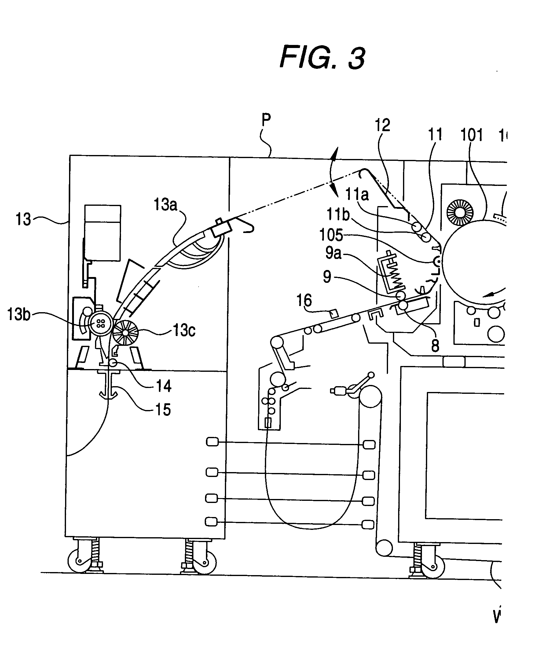
[0018] First, the whole configuration of an electrophotographic type printer applicable to a duplex printing system will be described using FIG. 3. In FIG. 3, W is a web. The web W is fed into an imaging part 10 by transporting rollers 8, 9. In the imaging part 10, an imaging device by, for example, an electrophotographic recording method is used and when a photosensitive drum 101 exemplified as an image carrier starts rotation, a high voltage is applied to a corona charger 102 and a surface of the photosensitive drum 111 is uniformly charged. In light outputted from a light source 103 made of a semiconductor laser or a light emitting diode, etc., image exposur...

second embodiment

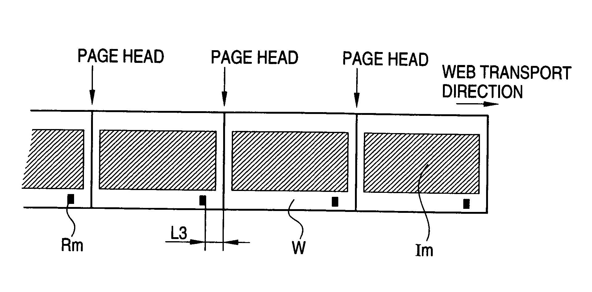
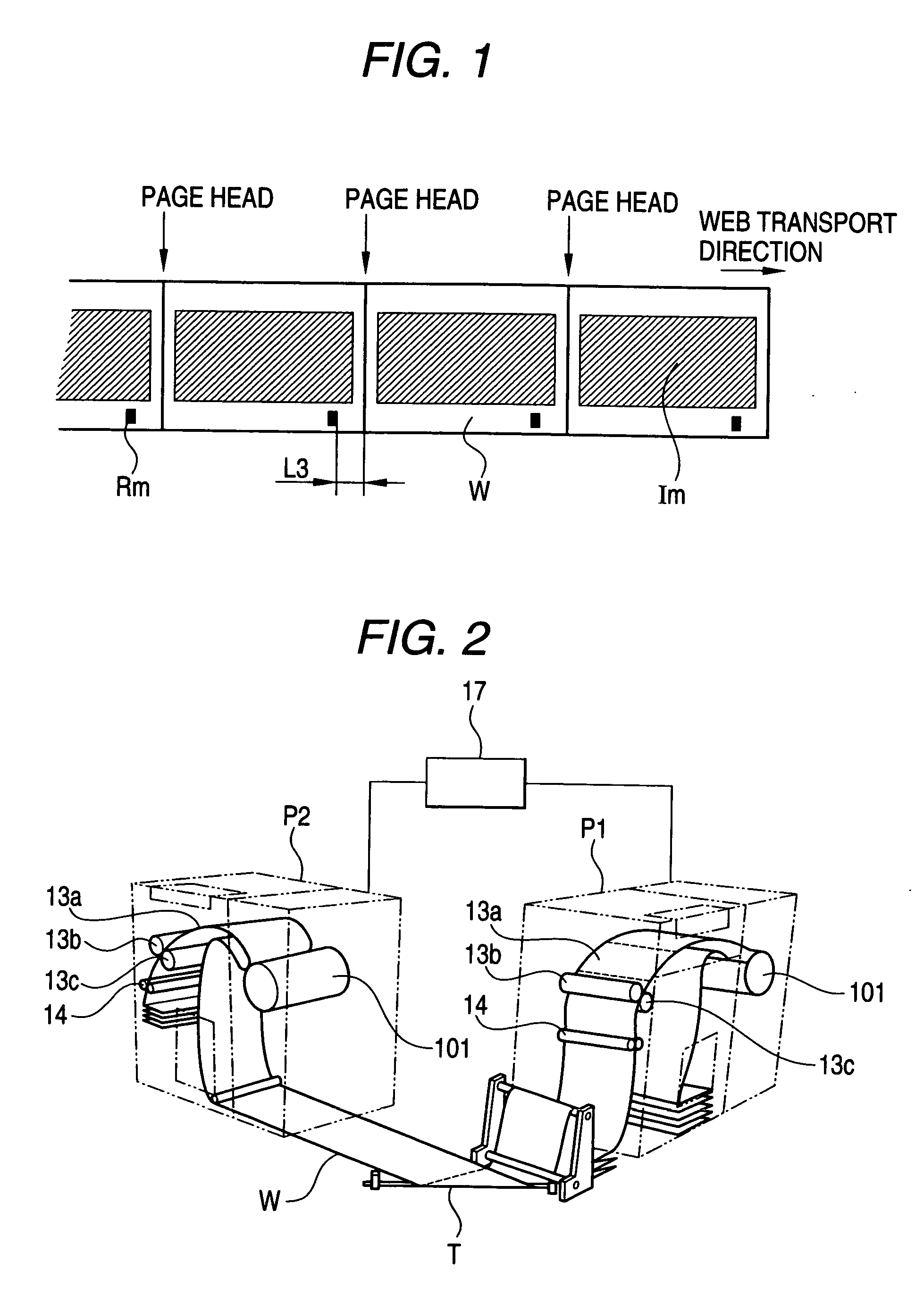
[0035] A method in which some marks previously printed on a web or a mark etc. used in control of a device for cutting a print result are used and a printer P1 does not form an alignment mark Rm again and an image of a first side is matched with an image of a second side will be described.

[0036] First, conditions on which this method can be used are that firstly, the marks can be detected by a mark sensor 16 and secondly, the marks are formed at equal intervals and at equal distances from the page heads.

[0037] A mark previously printed on a web or a mark for control of a cutting device is replaced with the alignment mark Rm and a distance L3 from the page head of the alignment mark Rm is set by a setting switch 18. Here, a numerical value measured by a measuring device actually may be used as the distance L3 from the page head of the alignment mark Rm, or the distance L3 can also be set automatically without using the setting switch 18, for example, when a controller 17 grasps the...


PUM


Abstract

An operator sets a distance from the page head of an alignment mark using a mark position setting switch mounted in a duplex printing system. A first printer forms the alignment mark in a position of the distance from the page head of a web, and reports position information about the alignment mark to a second printer. The alignment mark is detected by mark detection means of the second printer. Control means performs control of a web transport speed so that a phase between generation timing of a mark detection signal which the mark detection means generates by detecting the alignment mark and control timing calculated from alignment mark position data, alignment mark interval data and a web feed control signal generated at a preset period becomes constant.

Description

BACKGROUND OF THE INVENTION [0001] 1. Field of the Invention [0002] The present invention relates to a duplex printing system and a duplex printing method for forming an image etc. on double sides of a web, and particularly to a duplex printing system having an alignment control device for accurately aligning images of double sides. [0003] 2. Description of the Related Art [0004] As a printing system for forming an image on double sides of a web typified by long continuous band-shaped paper, a printing system constructed so that two printers are arranged in series and printing is done on the first side (front) of the web by the printer of a forward stage and the front and back of the web delivered from the printer of the forward stage are reversed by a reversing device and then the web is fed into the printer of a backward stage and printing is done on the second side (back) of the web by the printer of the backward stage has been proposed and commercialized. [0005] Recently, as the...

Claims


Application Information

Patent Timeline
Patent Type & Authority Applications(United States)
IPC IPC(8): B41J3/54B41J3/60B41J11/42B41J11/46B41J15/04B41J21/16B65H23/188G03G15/00G03G21/00G03G21/14G06F3/12
CPCB41J3/60B41J15/04B41J11/46
Inventor NAKAZAWA, SOUICHIINOUE, TAKAHIROMIYAMOTO, ATSUSHIMIZUNO, MASAHIRO
Owner RICOH KK
Why Eureka
Try Eureka