Electrical current measurements at head-disk interface

a head-disk interface and electric current technology, applied in the direction of magnetic recording, data recording, instruments, etc., can solve the problems of adversely affecting the operation of the hard-disk drive, increasing frequency of interference between the slider abs and the disk surface, and damage to the read-write head directly

Inactive Publication Date: 2005-08-11
SAE MAGNETICS (HK) LTD
View PDF9 Cites 47 Cited by
  • Summary
  • Abstract
  • Description
  • Claims
  • Application Information

AI Technical Summary

Benefits of technology

[0018] According to an embodiment of the present invention, electrical current is measured at the interface between the magnetic head slider and the magnetic medium. The presence of current between the medium (e.g., a magnetic recording disk) and the head slider is due to the presence of charge on the slider and disk and a discharge takes place during contact between the two. Such a current may also be due to triboelectric charge and discharge due to a head-disk contact event. This discharge current is very low and can be on the order of microamps or nanoamps. The measurement of the electrical current between the medium and the slider-head provides an accurate assessment of slider / disk contact events allowing the determination of the true glide or glide avalanche point of a disk and to identify magnetic head sliders that are contaminated (e.g., debris on the air bearing surface) are have flying heights that are too low for efficient operation.

Problems solved by technology

As the flying height of the slider decreases, interference between the slider ABS and the disk surface increases in frequency.
HDI can damage the read-write head directly, or cause catastrophic failure by disabling the air bearing.
Thus, it is assumed that if the measured flying height of the slider is too low, then there will be too much HDI, adversely affecting the operation of the hard-disk drive.
As stated above, however, the lower the flying height of the slider, the greater the data capacity for the drive.
One problem seen with using a flying height tolerance to control HDI is that as the flying height of conventional sliders is reduced, the tolerances become tighter.
Variations in surface topography for the disk and slider, vibration in both surfaces, and debris / lubricant accumulating, migrating, and dropping off both surfaces add complexity to the measurement of flying height at any particular time.
As sliders have become smaller and smaller, it becomes more difficult to include traditional spacing transducers such as capacitance probes, photonic probes, etc.
Furthermore, testing the flying height of a slider over a transparent disk as is known in the art causes additional problems.
Also, the measurement resolution of the flying height at such a low flying height can be very poor, and measurement of flying height over the transparent disk can cause contamination of the slider or electrostatic discharge (ESD) damage.
To implement this method of measuring magnetic spacing requires relatively expensive equipment and does not guarantee that other parts of the slider have impacted the disk.
The equipment needed to measure these parameters can be expensive and may not be able to detect mild head-disk interference.
Because of this low separation distance between the head slider and the disk, head-disk contacts are unavoidable.
Head-disk contact events may lead to read / write errors, head slider damage, disk damage, and general disk drive failure.
There are several problems using the glide head of the prior art.
This leads to a calibration signal which may underestimate the energy present during an actual head-disk contact event in a real drive (leading to missed head-disk contact events or a higher glide yield).
Though it is important to control the surface roughness of the air-bearing slider to minimize head-disk contact events, sliders may not be tested for this feature.
This is due, in part, to the possibility of electro-static shock discharge (ESD) damaging the slider during the test.
The DET test, however, cannot be readily used for detecting head-disk contact due to surface protrusion or the presence of particles on the slider head.
As to acoustic emission, as described above, air bearing resonance can interfere with the accuracy of the measurements.

Method used


Image

  • Electrical current measurements at head-disk interface
  • Electrical current measurements at head-disk interface
  • Electrical current measurements at head-disk interface

Examples


first embodiment

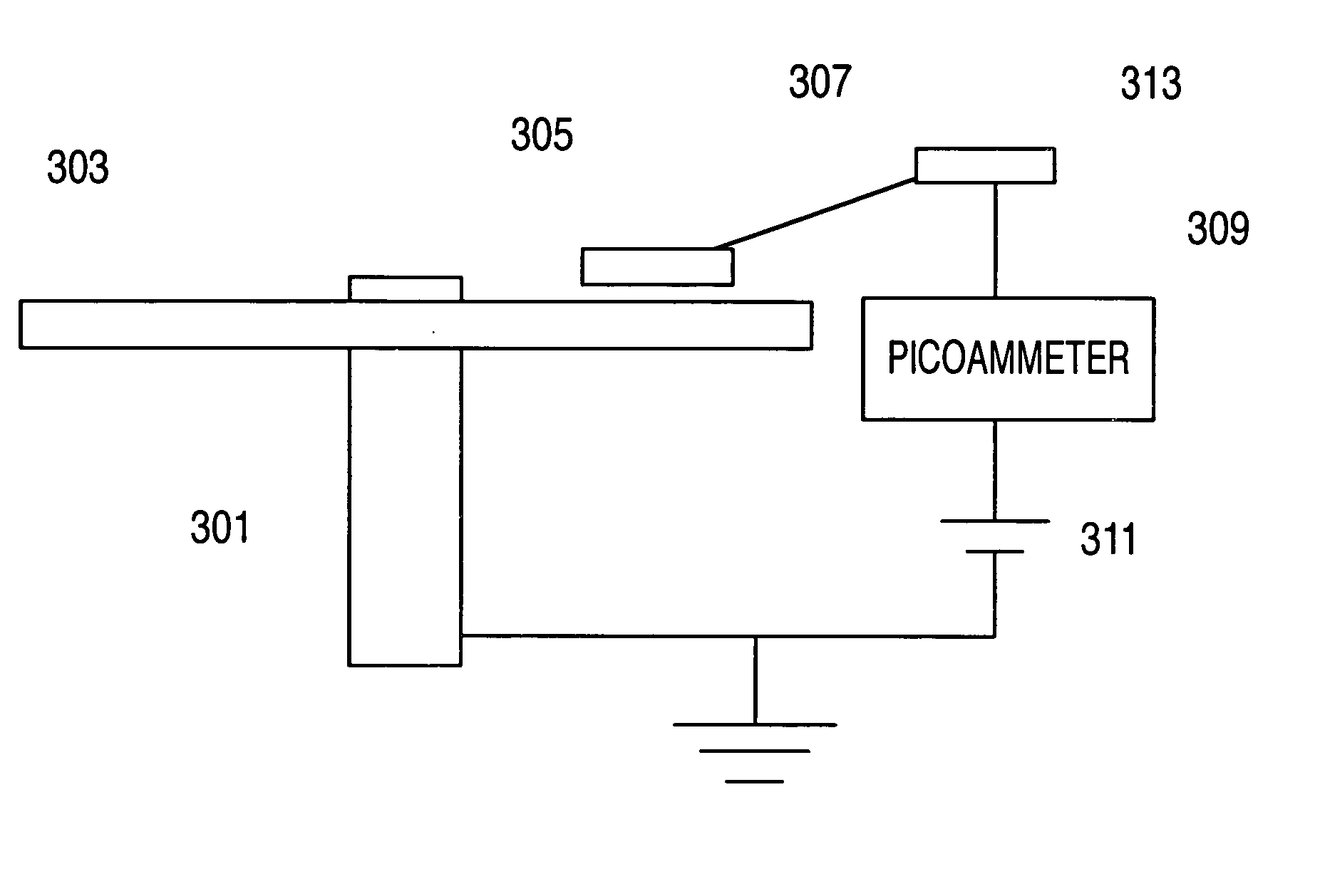
[0026] In the present invention, the head gimbal assembly (HGA, including the head 305 and its supporting flexure) is electrically isolated from ground. The ammeter 309 would be connected to contact 313 which is electrically connected over suspension 307 to the magnetic recording head. As seen in FIG. 3, if the HGA is electrically isolated from ground, then the ammeter 309 would detect electric current flowing between the disk and the head, such as would occur during contact events.

second embodiment

[0027] In a second embodiment, the ammeter 309 is coupled to the slider 305 through a wire separate from the suspension 307 (not shown specifically in FIG. 3). Again, the recording head / slider is electrically isolated from ground, and the ammeter 309 would measure current between the head 305 and the recording medium 303. This embodiment may provide a lower capacitance and, thus, more sensitivity to the current measurement.

[0028] In the embodiments above, the model 6487 picoammeter / voltage source is amenable to measure a somewhat constant low-level current, such as one that may be seen for multiple head-disk contact events each revolution. The model 428 current amplifier by the same manufacturer may be better for situations where the current is more transient (e.g., due to contact between the head and a particle on the disk).

[0029] Whether to use a bias voltage in the measurement of current between the head / slider and the disk depends on the flying height and the nature of the head...


PUM

PropertyMeasurementUnit
flying heightaaaaaaaaaa
external voltageaaaaaaaaaa
current amplitudeaaaaaaaaaa

Abstract

According to an embodiment of the present invention, head/disk contact events are determined through a measurement of current at the head disk interface. For example, an ammeter/voltage source component may be electrically coupled to a magnetic/slider of a disk drive as well as to a spindle coupled to the recording medium. Applied voltage to the slider may result in a lower flying height. Greater measured current by the ammeter could indicate head/disk contact and assist in adjusting applied voltage to obtain a desire flying height.

Description

FIELD OF THE INVENTION [0001] The present invention pertains to a method and apparatus for measuring current in hard disk drives and the like. More particularly, the present invention pertains to measuring electric current between a magnetic recording head and the recording medium. BACKGROUND OF THE INVENTION [0002] Hard disk drives are common information storage devices essentially consisting of a series of rotatable disks that are accessed by magnetic reading and writing elements. These data transferring elements, commonly known as transducers, are typically carried by and embedded in a slider body that is held in a close relative position over discrete data tracks formed on a disk to permit a read or write operation to be carried out. In order to properly position the transducer with respect to the disk surface, an air bearing surface (ABS) formed on the slider body experiences a fluid air flow that provides sufficient lift force to “fly” the slider and transducer above the disk ...

Claims


Application Information

Patent Timeline
Patent Type & Authority Applications(United States)
IPC IPC(8): G11B5/012G11B5/02G11B5/40
CPCG11B5/40G11B5/02
Inventor ZHANG, XIAOFENGFENG, ZHUCHA, ELLIS T.FU, YEN
Owner SAE MAGNETICS (HK) LTD
Why Eureka
Try Eureka