Image decoding apparatus

a decoding apparatus and image technology, applied in the field of image decoding apparatus, can solve the problems of increasing circuitry scale and control complexity, difficult to implement parallelization and sequential processing, and increasing the number of candidates, so as to facilitate parallelization and high versatility of use.

Inactive Publication Date: 2005-08-11
SANYO ELECTRIC CO LTD
View PDF4 Cites 47 Cited by
  • Summary
  • Abstract
  • Description
  • Claims
  • Application Information

AI Technical Summary

Benefits of technology

[0013] The present invention has been made in view of the foregoing circumstances and problems, and an object thereof is to provide an image decoding technology capable of decoding at high speed. Another object thereof is to provide an image decoding technology that facilitates parallelization. Still another object thereof is to provide an image decoding technology that has high versatility of uses.
[0022] By employing a structure according to this preferred embodiment, when a parallel processing of coded image data is possible, the coded image data are decoded by a plurality of decoding units in parallel. Thus, the decoding processing can be carried out at high speed. Even if the parallel processing is not possible, the first decoding unit of high specifications carries out the decoding processing independently, so that the high versatility of uses is achieved.
[0024] There may be provided a plurality of decoding units each of which is comprised of the first decoding unit and the at least one second decoding unit. Thereby, the decoding processing can be performed faster.
[0025] When a decoding processing is performed in parallel, the first decoding unit may decode data having a certain property exclusively. The first decoding unit may carry out two modes, namely, a first mode by which to decode the coded image data independently if a parallel processing is not possible and a second mode by which to decode data of a certain property exclusively if the parallel processing is implemented. According to this structure and operation achieved thereby, the first decoding unit is provided with a function of exclusively decoding data of a certain property and this function accounts for part of the second decoding unit, so that the number of the second decoding units can be reduced by one. Thus, this structure contributes to both further speed-up and the reduction of circuit area.

Problems solved by technology

In decoding, however, peripheral information on pixels is not known until decoding is actually done, so that it is difficult to implement parallelization and the processing must be done sequentially.
Another problem with this apparatus is that parallel processing with it may result in an exponential increase in the number of candidates for context, which in turn causes an increase in circuitry scale and complexity of control.
On the other hand, for data coded by the latter method, decoding cannot be carried out independently for each pass.

Method used


Image

  • Image decoding apparatus
  • Image decoding apparatus
  • Image decoding apparatus

Examples


first embodiment

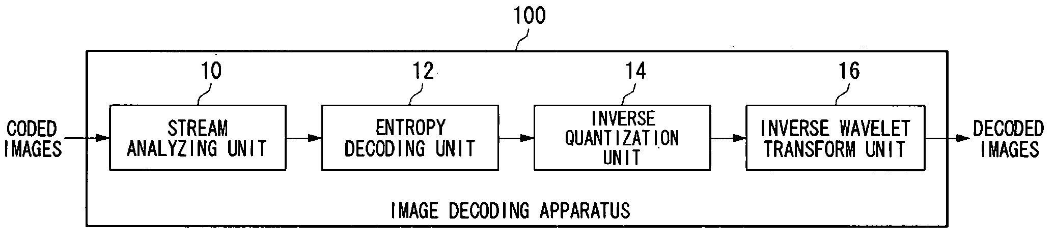
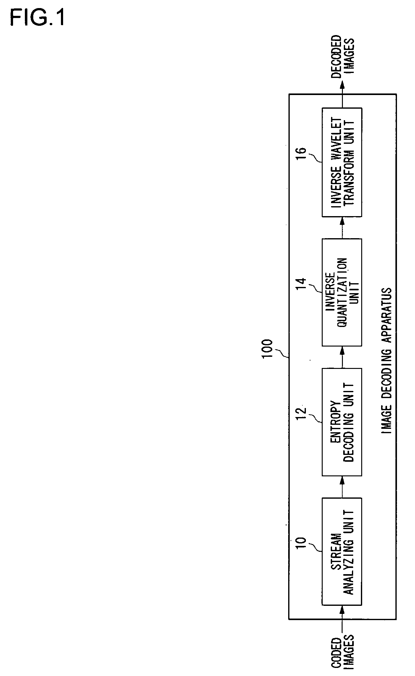
[0061]FIG. 1 illustrates a structure of an image decoding apparatus 100 according to a first embodiment of the present invention. In terms of hardware, this structure of image decoding apparatus 100 can be realized by a CPU, a memory and other LSIs of an arbitrary computer. In terms of software, it can be realized by memory-loaded programs which have decoding functions or the like, but drawn and described herein are function blocks that are realized in cooperation with those. Thus, it is understood by those skilled in the art that these function blocks can be realized in a variety of forms such as by hardware only, software only or the combination thereof.

[0062] The image decoding apparatus 100 receives the input of images that have been compressed and coded, decodes the inputted coded images and then outputs the decoded images. The coded images are produced in the following manner. That is, an original image is recursively divided into four frequency sub-bands and is then subjecte...

second embodiment

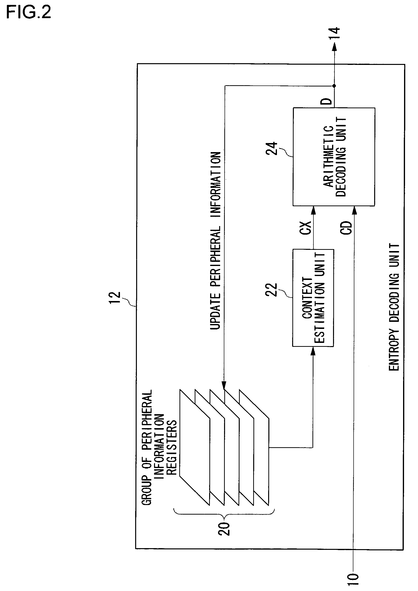
[0102]FIG. 13 illustrates a structure of an entropy decoding unit 12 in an image decoding apparatus according to a second embodiment of the present invention. The image decoding apparatus according to this second embodiment is the same as an image decoding apparatus 100 according to the first embodiment except for the structure of an entropy decoding unit 12.

[0103] In an entropy decoding unit 12 according to this second embodiment, a context register 23 for holding a context label CX calculated in advance by a context estimation unit 22 is provided immediately after the context estimation unit 22.

[0104] In a group of peripheral information registers 20, the contents to be held by the respective registers are updated as appropriate, receiving the feedback of decision D derived from the decoding of coded data CD by an arithmetic decoding unit 24. The context estimation unit 22 refers to the group of peripheral information registers 20, which is thus updated, in order to estimate the...

third embodiment

[0106]FIG. 14 illustrates a structure of an entropy decoding unit 12 in an image decoding apparatus according to a third embodiment of the present invention. The image decoding apparatus according to this third embodiment is also the same as an image decoding apparatus 100 according to the first embodiment except for the structure of an entropy decoding unit 12.

[0107] The entropy decoding unit 12 according to this third embodiment performs decoding by scanning the stripes of bit-planes. In doing so, however, it does not decode by scanning all the coefficients but decodes only by specifying the positions of coefficients to be decoded.

[0108] A decoding position calculating unit 27 calculates the positions of coefficients to be decoded in each processing pass by referring to the peripheral information stored in a group of peripheral information registers 20.

[0109]FIGS. 15A to 15C illustrate how decoding positions are calculated by the decoding position calculating unit 27. FIG. 15A ...


PUM


Abstract

Coded data are inputted from a stream analyzing unit to an entropy decoding unit. A group of peripheral information registers stores peripheral information on a target pixel for estimating a context used for arithmetic decoding of the coded data. Based on the peripheral information stored in the group of peripheral registers, a context estimation unit estimates a context and delivers the estimated context to an arithmetic decoding unit. The arithmetic decoding unit decodes the coded data based on a context label, then derives a decision and supplies the decision to an inverse quantization unit. The peripheral information stored in the group of peripheral registers is updated by a decoding result of the arithmetic decoding unit in the same cycle as the decoding.

Description

BACKGROUND OF THE INVENTION [0001] 1. Field of the Invention [0002] The present invention relates to image decoding apparatus, and it particularly relates to a decoding apparatus for decoding coded image data that contain a group of data having a plurality of properties. [0003] 2. Description of the Related Art [0004] At ISO / ITU-T, JPEG2000 using a discrete wavelet transform (DWT) is being standardized as a successor to JPEG (Joint Photographic Expert Group), which is a standard technology for compression and coding of still images. In JPEG2000, a wide range of image quality, from low bit-rate coding to lossless compression, can be coded highly efficiently, and a scalability function, in which the image quality is gradually raised, can be realized easily. [0005] The coding processing in JPEG2000 includes block division processing, coefficient bit modeling processing and arithmetic coding processing. In block division processing, sub-bands generated by performing a discrete wavelet t...

Claims


Application Information

Patent Timeline
Patent Type & Authority Applications(United States)
IPC IPC(8): G06K9/36H03M7/00H04N7/26
CPCH04N19/13H04N19/63H04N19/436H04N19/44H04N19/42H04N19/61
Inventor WATANABE, TSUYOSHIOKADA, SHIGEYUKI
Owner SANYO ELECTRIC CO LTD
Why Eureka
Try Eureka