Image forming apparatus

a technology of forming apparatus and fixing device, which is applied in the direction of electrographic process apparatus, instruments, optics, etc., can solve the problems of increasing the thermal capacity of the apparatus, affecting the usability of the apparatus for users, and requiring a certain amount of power supply to the fixing devi

Inactive Publication Date: 2005-08-11
RICOH KK
View PDF12 Cites 45 Cited by
  • Summary
  • Abstract
  • Description
  • Claims
  • Application Information

AI Technical Summary

Benefits of technology

[0020] An image forming apparatus according to still another aspect of the present invention includes a condenser; a reading unit that reads images of a plurality of documents one-by-one; a heating unit that applies heat to an unfixed image that corresponds to the images read by the reading unit; and a power-controlling unit that causes the condenser to supply power to the heat

Problems solved by technology

In recent years, an environmental issue has become important, which leads to energy saving in the image forming apparatus such as copy machine and printer.
However, when the energy consumption is made zero during standby, a long heating time, for example, a few minutes to over ten minutes is needed to raise the temperature to a usable temperature of approximately 180 degrees C. because a metal roller made of, for example, iron or aluminum is mainly used for the heat roller of the fixing device, and therefore the thermal capacity is large.
Such a waiting time worsens the usability of the apparatus for a user.
However, a certain amount of power must be supplied to the fixing device even when the fixing device is not in use.
Thus, extra energy is disadvantageously consumed, and energy saving is not sufficient.
Further, the technology does not aim at increasing the maximum supplied power at the startup more than the power supplied from the main power source.
Therefore, battery exchange is carried out more frequently, which makes a trouble and increases a running cost such as cost of batteries to be exchanged.
Furthermore, lead-acid batteries use liquid sulfuric acid for electrolyte and so forth, and therefore, there is also an undesirable aspect that they are not suitable for office machines.
Still further, there are problems that not only is the load to the heating circuit built in the heat roller increased by an abrupt current change, inrush power, and the like but also noise is generated owing to flow of the inrush current to peripheral circuits when supply of large power is starte

Method used


Image

  • Image forming apparatus
  • Image forming apparatus
  • Image forming apparatus

Examples


Embodiment Construction

[0027] Exemplary embodiments of the present invention are explained below with reference to accompanying drawings.

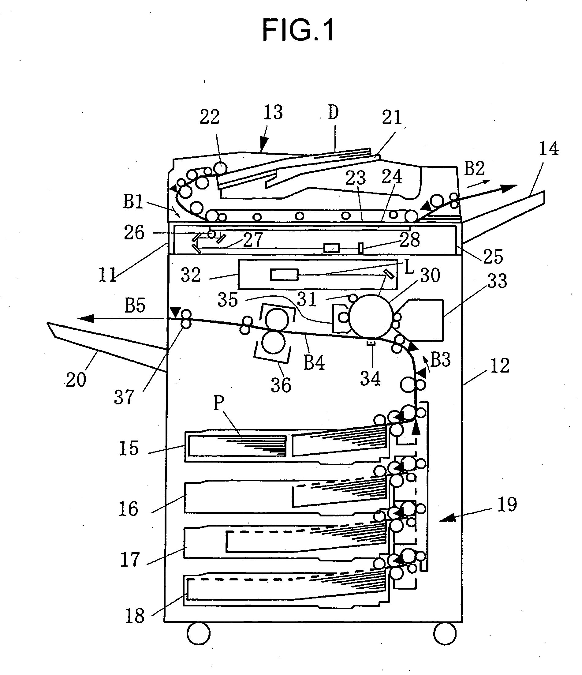
[0028]FIG. 1 is a cross sectional view of an image forming apparatus such as copy machine and printer of electrophotographic system according to the present invention. The image forming apparatus of the present embodiment is capable of feeding continuously, for example, 100 sheets of paper (75 copies per minute (CPM)). The image forming apparatus is composed of, in its main structure, a reading unit 11 that reads a document, an image forming unit 12 that forms an image, an automatic document feeder (ADF) 13, a paper delivery tray 14 that stacks documents sent out of the ADF 13, a paper feeder 19 provided with paper feeding cassettes 15 to 18, and a paper delivery tray 20 that stacks recording paper. For example, the maximum feeding capacity of paper that the ADF 13 can feed is 100 sheets of paper, and a reading time taken for the reading unit 11 to read 100 sheets of do...


PUM


Abstract

Power is supplied from a capacitor of an auxiliary power source to a secondary heating element of a heating unit, thereby preventing temperature drop of a fixing roller at the time of continuous paper delivery. An allowable range for starting discharge from the capacitor is set to, for example, 30 to 40 volts. A discharge time in which the voltage of the capacitor reduces to a termination value, such as 20 volts, is longer than a time necessary for a reading unit to read a maximum number (for example, 100 sheets) of documents that can be read at one time.

Description

CROSS-REFERENCE TO RELATED APPLICATIONS [0001] The present document incorporates by reference the entire contents of Japanese priority document, 2004-029259 filed in Japan on Feb. 5, 2004. BACKGROUND OF THE INVENTION [0002] 1) Field of the Invention [0003] The present invention relates to an image forming apparatus (such as copy machine, printer, and facsimile) that has a minimum number of condensers (such as capacitor) to prevent temperature drop of a fixing device (such as fixing roller) due to continuous paper delivery. [0004] 2) Description of the Related Art [0005] An image forming apparatus, such as copy machine that forms an image on a recording medium such as ordinary paper and over head projector (OHP), frequently employs the electrophotographic system in view of high-speed, image quality, cost, and the like. The electrophotographic system is a method in which a toner image is formed on a recording medium, and the formed toner image is fixed on the recording medium by heat ...

Claims


Application Information

Patent Timeline
IPC IPC(8): G03G15/20
CPCG03G15/80G03G15/2039
Inventor MATSUSAKA, SUSUMUKISHI, KAZUHITOKATO, YASUHISAAMITA, AKIYASUOKAMOTO, MASAMITSUKIOKA, YASUTADATAKAGI, HIROMASA
Owner RICOH KK
Why Eureka
Try Eureka