
Bright formable metalized film laminate

Inactive Publication Date: 2005-08-11
AVERY DENNISON CORP
View PDF42 Cites 33 Cited by
  • Summary
  • Abstract
  • Description
  • Claims
  • Application Information

AI Technical Summary

Benefits of technology

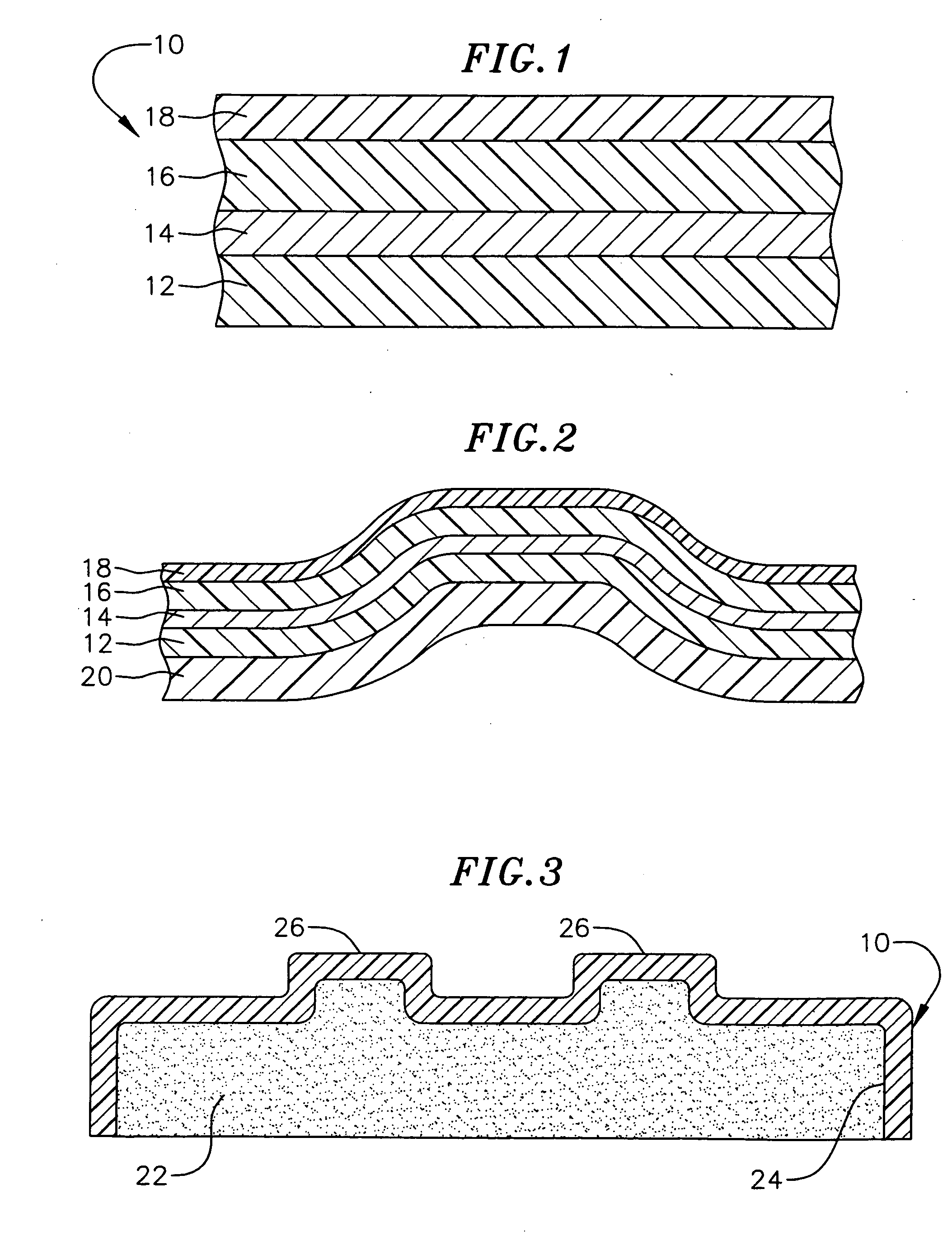
[0008] Briefly, one embodiment of the invention comprises a bright metal laminate which includes a highly reflective metal layer applied to a supporting baseweb layer comprising a flexible thermoplastic and thermoformable polyurethane film. The metal layer comprises indium or an alloy of indium and is applied to the surface of the baseweb by vapor deposition techniques. An optically clear polymeric outer layer preferably containing an acrylic, polycarbonate, or PETG resin is laminated in free-film form and under heat and pressure to the exposed surface of the metalized film supported on the baseweb. The lamination step bonds the outer layer to the metal layer but also enhances reflectivity of the metal. The polyurethane baseweb promotes adhesion of the metal layer to the baseweb in the absence of an intervening bonding layer or surface treatment, while lamination smoothes out the metal layer to a mirror-like finish that produces a reflective laminate having a distinctness-of-image greater than 95. The laminate can be thermoformed to a three-dimensional shape while retaining its high level of distinctness-of-image over 95. Highly reflective shaped articles having excellent optical clarity and DOIs over 99 can be produced.

Problems solved by technology

Some reflective metal laminates are not adequately thermoformable to a three-dimensional shape.
Such reflective metal laminates, when formed to a three-dimensional shape, lose their flexibility, causing the metal layer to fracture or suffer loss of reflectivity.
Inter-layer adhesion problems such as delamination also can develop during such forming or otherwise during use.

Method used


Image

  • Bright formable metalized film laminate

Examples


example 1

[0042] An 8 mil urethane sheet supported on one side by a polyester carrier was placed in a bell jar vacuum metalization apparatus. A 0.06 gram piece of indium was then placed in an evaporation boat. A vacuum was drawn and an electric current was applied to the evaporation boat. The indium piece melted by vaporization and was deposited on the urethane sheet. The vacuum chamber was vented and the sample removed. Urethane sheets of 2, 3 and 6 mil thickness were also used successfully in this process.

[0043] Clear sheets of thermoplastic material such as polycarbonate and acrylic resin were cut to the same size as the 8 mil urethane sheet. A thickness range of the clear sheet was between 10-20 mils although the acrylic as thin as 2.5 mils was used successfully. For the polycarbonate sheet a PVDF / acrylic over-laminate was laminated to the outer surface. The overlaminate comprised Kynar 500 Plus PVDF and Elvacite 2042 from Ineos. The metalized side of the urethane sheet was placed on the...

example 2

[0046] A 2 mil urethane baseweb was metalized in line. A roll of 2 mil urethane film supported by a polyester carrier was placed in a vacuum metallization apparatus. The urethane roll was 19 inches wide. Four rolls of indium wire were also placed in the apparatus. The wire was unwound and fed into four evaporation boats. A vacuum was drawn in the apparatus, and an electric current was applied to the boats. The indium wire melted and was vaporized under the vacuum. The wire was fed continuously into the boats, and the vaporized indium was deposited on the urethane as it was unrolled. After the entire roll was coated, the vacuum chamber was vented and the roll removed.

[0047] A clear roll of thermoplastic polycarbonate was slit to the same width as the roll of metalized 2 mil urethane. The polycarbonate thickness was 7 mils. The metalized side of the 2 mil urethane film was heat and pressure laminated to the polycarbonate sheet. This resulted in a permanent bond between the metalized ...

example 3

[0049] Samples of the construction described in Example 2 were placed in accelerated weathering apparatuses, including Xenon Weatherometer and QUV. After approx. 500 hours exposure, a haze developed on the surface of the samples. The haze grew progressively worse with time. It was believed that the haze might be UV absorber migrating to the surface of the PVDF / acrylic overlaminate film. This haze also occurred in outdoor Florida exposure after 6 months.

[0050] To solve this problem, an L9 design of experiments (DOE) was conducted to evaluate different UV absorbers in the PVDF / acrylic coating. Tinuvin 400, Tinuvin 928, and Tinuvin 900 (control) were evaluated. The same PVDF / acrylic resins as Examples 1 and 2, at the same ratio, were used. PVDF / acrylic topcoat thicknesses of 0.5, 1.0, and 2.0 mils were evaluated.

[0051] After 500 hours exposure, the L9 samples were compared. Samples with the Tinuvin 400 and 928 showed superior results to the Tinuvin 900 samples, with respect to preven...


PUM

PropertyMeasurementUnit
Temperatureaaaaaaaaaa

Abstract

A bright metal laminate comprises a highly reflective metal layer applied to a supporting baseweb comprising a flexible thermoplastic and thermoformable polyurethane film. The metal film comprises indium or an alloy of indium and is applied to a surface of the baseweb by vapor deposition techniques. An optically clear polymeric outer layer of preferably acrylic, PETG or polycarbonate resin is laminated in free-film form to the exposed surface of the metalized film under heat and pressure to bond the outer layer to the metal film. The surface of the polyurethane baseweb is sufficient to produce adhesion of the metal layer to the baseweb in the absence of an intervening bonding layer or surface treatment, while smoothing out the metal layer to a mirror-like finish under lamination to produce a reflective laminate having a distinctness-of-image (DOI) greater than 95. The laminate can be thermoformed to a three-dimensional shape while retaining its high DOI level.

Description

CROSS REFERENCE TO RELATED APPLICATIONS [0001] This application is a continuation-in-part of application Ser. No. 10 / 429,015, filed May 2, 2003.FIELD OF INVENTION [0002] This invention relates to bright metalized film laminates, and more particularly, to a formable metal laminate having a high degree of reflectivity, in which the laminate can be thermoformed to a three-dimensional shape while retaining a mirror-like appearance. BACKGROUND [0003] Highly reflective metalized polymeric laminates can be used as substitutes for reflective metal parts having chrome-plated surfaces. The automotive industry is an example where decorative metalized polymeric laminates have been used as substitutes for chrome-plated exterior parts such as trim parts, body side moldings, emblems or badges, and the like. Decorative metal laminates also can be used for interior automotive parts such as on dashboards, for example. [0004] Decorative metalized polymeric laminates have been used successfully in the ...

Claims


Application Information

Patent Timeline
IPC IPC(8): B32B27/08B44C1/14B44C3/02B60R13/00B60R13/02B60R13/04
CPCB32B27/08B44C1/14B44C3/025B60R13/04B60R13/005B60R13/02B60R13/00Y10T428/31551Y10T428/31786B32B27/365B32B27/40B32B2255/10B32B2255/205B32B2307/406B32B2307/416B32B2307/536B32B2605/00
Inventor JOHNSON, JOHN R.
Owner AVERY DENNISON CORP
Learn More