Steel automotive drive shaft with carbon fiber liner

a technology of drive shaft and carbon fiber liner, which is applied in the direction of shaft and bearing, shaft assembly, rotary machine parts, etc., can solve the problems of vibration and frequency resonance within, noise generation, deleterious affecting structural integrity, etc., and achieve the effect of high modulus of elasticity

a technology of drive shaft and carbon fiber liner, which is applied in the direction of shaft and bearing, shaft assembly, rotary machine parts, etc., can solve the problems of vibration and frequency resonance within, noise generation, deleterious affecting structural integrity, etc., and achieve the effect of high modulus of elasticity

US20050176513A1Inactive Publication Date: 2005-08-11ILLINOIS TOOL WORKS INC

Image

  • Steel automotive drive shaft with carbon fiber liner
  • Steel automotive drive shaft with carbon fiber liner

Examples


Embodiment Construction

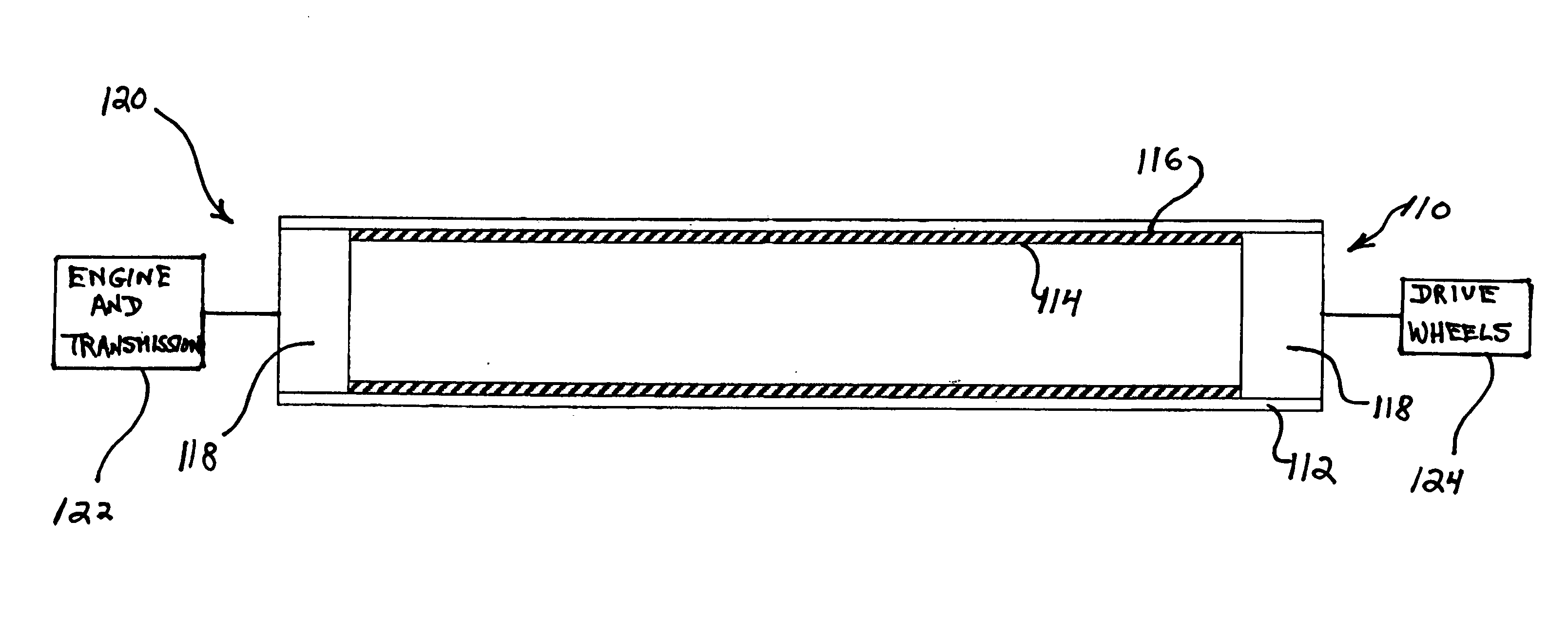
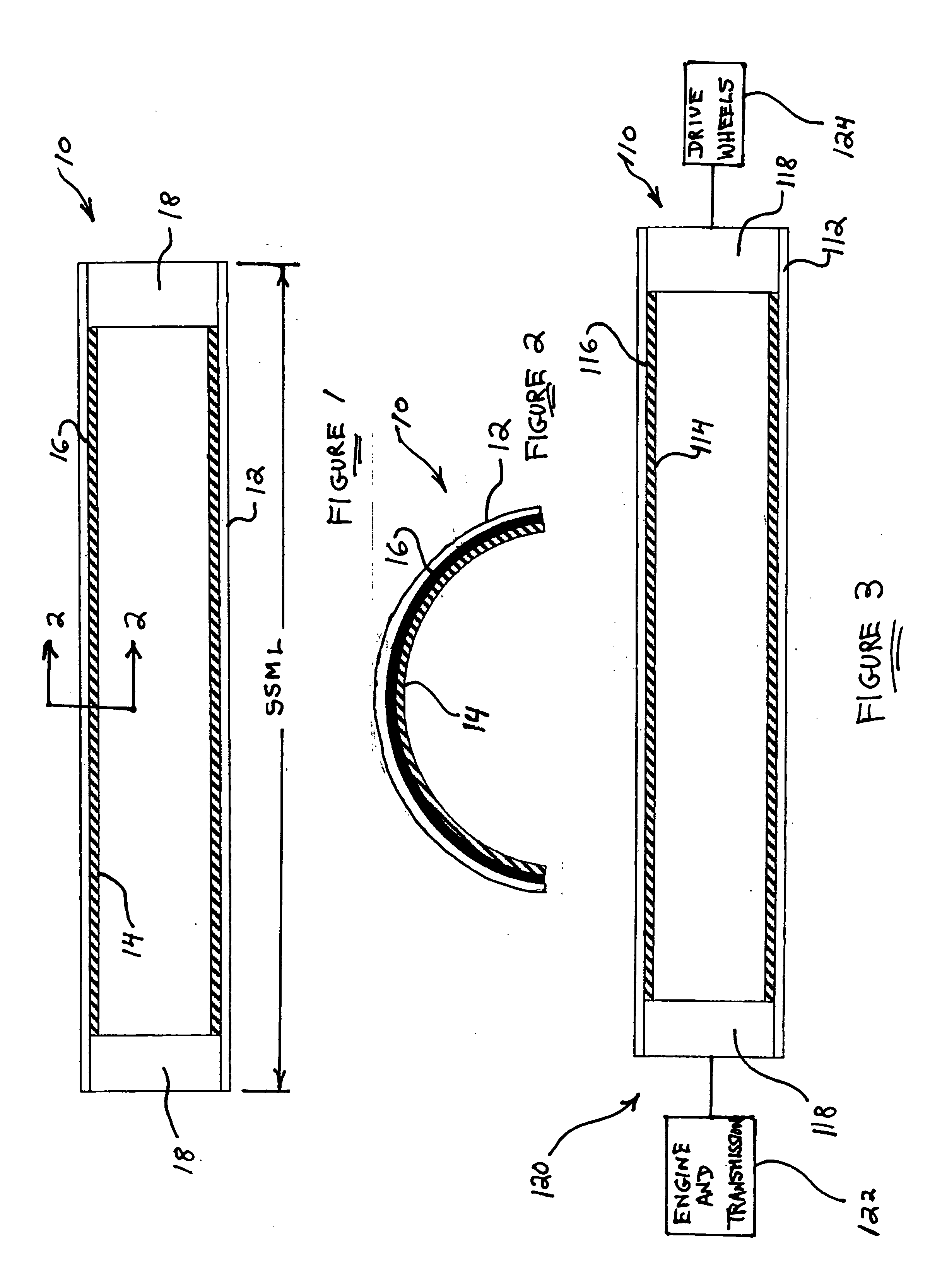
[0012] Referring now to the drawings, and more particularly to FIGS. 1 and 2 thereof, a new and improved composite rotary steel drive shaft, constructed in accordance with the principles and teachings of the present invention, is disclosed and is generally indicated by the reference character 10. More particularly, the new and improved composite rotary steel drive shaft 10 is seen to comprise a radially outer tubular steel shaft member 12, and a radially inner carbon fiber tubular liner 14, wherein the radially inner carbon fiber tubular liner 14 is adapted to be fixedly or permanently bonded to the inner peripheral wall surface of the radially outer tubular steel shaft member 12 by means of a suitable adhesive, resin, or the like, which is illustrated at 16. It is to be noted that, as a result of the bonding of the radially inner carbon fiber tubular liner 14 upon the inner peripheral wall surface of the radially outer tubular steel shaft member 12, not only are the radially outer ...


PUM


Abstract

A new and improved composite rotary steel drive shaft comprises a radially outer steel tubular member and a radially inner carbon fiber tubular liner which is adhesively bonded upon the inner peripheral wall surface of the radially outer steel tubular member wherein the carbon fiber tubular liner is characterized by or exhibits a relatively high modulus of elasticity. As a result of the adhesive bonding of the radially inner carbon fiber tubular liner upon the inner peripheral wall surface of the radially outer steel tubular member, the torsional stiffness properties of the resulting composite rotary steel drive shaft are dramatically increased to such a degree that high-performance, high-speed rotary operation of the same, within the range of ten thousand revolutions per minute (10,000 RPM), is enabled without the composite rotary drive shaft experiencing any undesirable deflections, or any detrimental vibrational resonance, as has been characteristic of conventional rotary drive shafts. In addition, in view of the fact that the radially outer member of the composite rotary steel drive shaft comprises a radially outer steel tubular member, the resulting composite rotary steel drive shaft is considered to be a steel rotary drive shaft and is therefore acceptable to, and is able to be sanctioned by various professional automotive racing authorities.

Description

FIELD OF THE INVENTION [0001] The present invention relates generally to drive shafts, in particular, to rotary drive shafts for use within automotive powertrain systems, and more particularly to a new and improved high-performance, high-speed rotary drive shaft for use within automotive powertrain systems wherein the rotary drive shaft is fabricated as a composite or hybrid structure comprising a radially outer steel tubular shaft and a radially inner carbon-fiber tubular shaft which is bonded to the internal peripheral surface of the radially outer steel tubular shaft, whereby the integrally bonded presence of the radially inner carbon-fiber tubular shaft within the radially outer steel tubular shaft not only permits such rotary drive shaft to meet original equipment manufacturing (OEM) specifications required, for example, by automotive racing authorities, such as, for example, NASCAR® (National Association for Stock Car Auto Racing), but in addition, permits such rotary drive sh...

Claims


Application Information

Patent Timeline
11 Aug 2005
Publication
US20050176513A1
IPC
F16C3/02
CPC
F16C3/02; F16C3/023; F16C2226/40
Inventors
RAYMOND, STEVEN L.; VILLALPANDO, JAMES R.