System and method for delivering a left atrial appendage containment device

a technology of containment device and left atrial appendage, which is applied in the field of system and method for delivering a left atrial appendage containment device, can solve the problems of irregular and turbulent blood flow in the vascular system, rapid and chaotic heartbeat that produces lower cardiac output, and patients with atrial fibrillation typically have a significantly decreased quality of life, and fail to contract with any vigor

Inactive Publication Date: 2005-08-11
BOSTON SCI SCIMED INC
View PDF25 Cites 134 Cited by
  • Summary
  • Abstract
  • Description
  • Claims
  • Application Information

AI Technical Summary

Benefits of technology

[0011] There is provided in accordance with one embodiment of the present invention a method for containing emboli within a left atrial appendage of a patient. In one embodiment, an implant that has a frame that is expandable from a reduced cross section to an enlarged cross section is provided, the frame extending between a proximal hub and a distal hub. The frame is releasably coupled near its proximal hub to a control line extending proximally away from the proximal hub. A slider

Problems solved by technology

Embolic stroke is the nation's third leading killer for adults, and is a major cause of disability.
Atrial fibrillation is an arrhythmia of the heart that results in a rapid and chaotic heartbeat that produces lower cardiac output and irregular and turbulent blood flow in the vascular system.
A patient with atrial fibrillation typically has a significantly decreased quality of life due, in part, to the fear of a stroke, and the pharmaceutical regimen necessary to reduce that risk.
The LAA normally contracts with the rest of the left atrium during a normal heart cycle, thus keeping blood from becoming stagnant therein, but often fails to contract with any vigor in patients experiencing atrial fibrillation due to the discoordinate electrical signals associated with AF.
Pharmacological therapies for stroke prevention such as oral or systemic administration of warfarin or the like have been inadequate due to serious side effects of the medications and lack of patient compliance in taking the medication.
Invasive surgical or thorascopic techniques have been used to obliterate the

Method used


Image

  • System and method for delivering a left atrial appendage containment device
  • System and method for delivering a left atrial appendage containment device
  • System and method for delivering a left atrial appendage containment device

Examples


Embodiment Construction

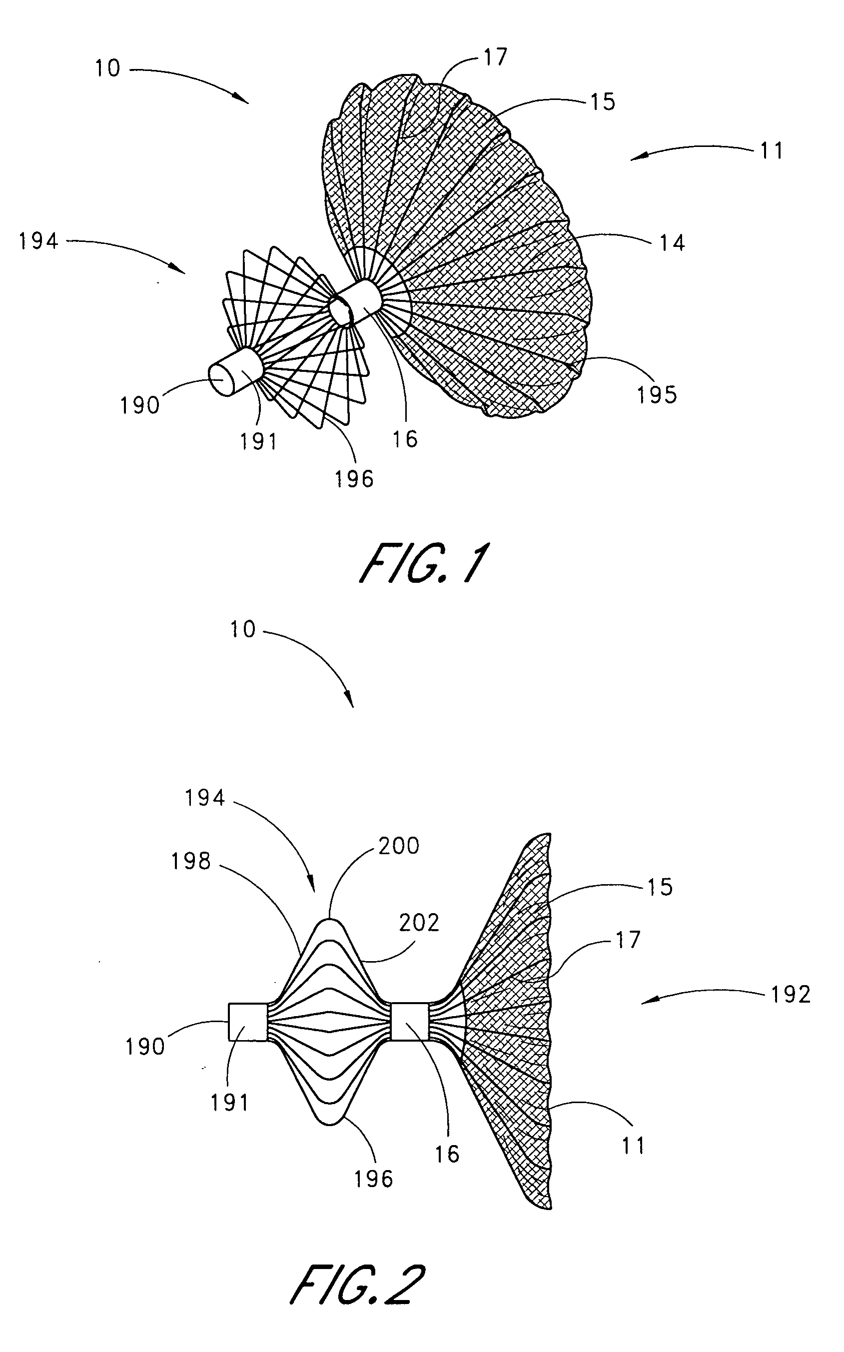
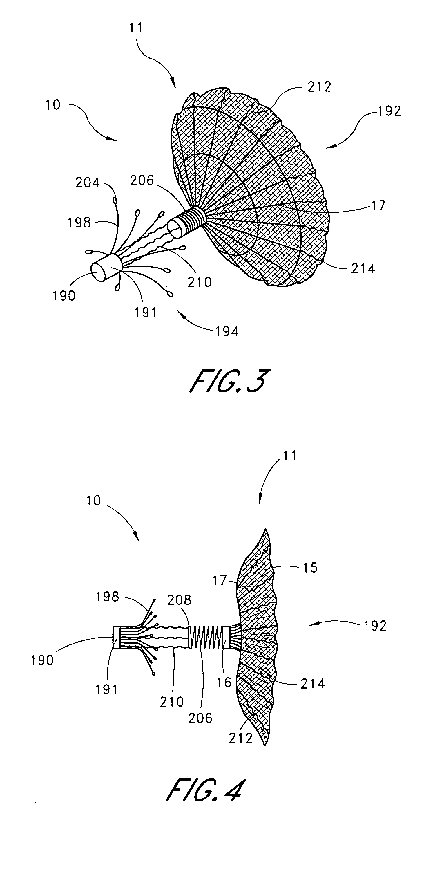
[0103] Referring to FIGS. 1 and 2, there is illustrated one embodiment of an occlusion or containment device 10 in accordance with the present invention. Although the present invention will be described primarily in the context of an occlusion device, the present inventors also contemplate omitting the fabric cover or enlarging the pore size to produce implantable filters or other devices which are enlargeable at a remote implantation site. The terms “occlusion device” or “containment device” are intended to encompass all such devices.

[0104] The occlusion device 10 comprises an occluding member 11 comprising a frame 14 and a barrier 15. In the illustrated embodiment, the frame 14 comprises a plurality of radially outwardly extending spokes 17 each having a length within the range of from about 0.5 cm to about 2 cm from a hub 16. In one embodiment, the spokes have an axial length of about 1.5 cm. Depending upon the desired introduction crossing profile of the collapsed occlusion dev...


PUM


Abstract

A method of delivering and deploying the device for containing the emboli during a surgical procedure proximate to the heart. Access is gained to the heart and the left atrium such that a distal end of the delivery sheath can be located near the left atrial appendage. A distal end of a delivery catheter can be loaded with the device in a collapsed position and passed through the delivery sheath thereby delivering the device within the left atrial appendage. The device is expanded to contain emboli in the left atrium appendage.

Description

RELATED APPLICATIONS [0001] This application claims the priority benefit under 35 U.S.C. § 119(e) of the provisional application 60 / 526,960, filed Dec. 4, 2003, which is hereby incorporated by reference in its entirety.BACKGROUND OF THE INVENTION [0002] 1. Field of the Invention [0003] Embodiments of this invention relate in general to a system and method for delivering a left atrial appendage containment device. [0004] 2. Description of the Related Art [0005] Embolic stroke is the nation's third leading killer for adults, and is a major cause of disability. There are over 700,000 strokes per year in the United States alone. Of these, roughly 100,000 are hemorrhagic, and 600,000 are ischemic (either due to vessel narrowing or to embolism). The most common cause of embolic stroke emanating from the heart is thrombus formation due to atrial fibrillation. Approximately 80,000 strokes per year are attributable to atrial fibrillation. Atrial fibrillation is an arrhythmia of the heart tha...

Claims


Application Information

Patent Timeline
IPC IPC(8): A61B17/00A61B17/08A61B17/12
CPCA61B17/0057A61B2017/12054A61B17/12122A61B17/12172A61B2017/003A61B2017/00575A61B2017/00579A61B2017/00592A61B2017/00597A61B2017/00615A61B2017/00623A61B2017/00632A61F2/01A61F2/013A61F2230/0071A61F2230/008A61B2017/12095A61F2002/018A61F2230/0006A61B17/12022A61F2002/9665A61F2002/9511A61F2/2439A61F2/243A61F2002/9505
Inventor VAN DER BURG, ERIK J.KUME, STEWART M.
Owner BOSTON SCI SCIMED INC
Why Eureka
Try Eureka