Cutting structure for single roller cone drill bit

a cutting structure and drill bit technology, applied in drill bits, cutting machines, earthwork drilling and mining, etc., can solve the problems of more and less wear on the cutting element on the single cone bi

Inactive Publication Date: 2005-08-18
SMITH INT INC
View PDF14 Cites 47 Cited by
  • Summary
  • Abstract
  • Description
  • Claims
  • Application Information

AI Technical Summary

Problems solved by technology

One of the limitations of single cone roller bits is that the cutting elements tend to experience greater wear over time due to shearing action, compared to cutting elements on a two or three cone bits.
Shearing rock typically causes more wear on a cutting element than impacting the rock to compressively fail it.
However, as a result, the wear of the cutting elements on a single cone bit is typically not uniform.
Therefore, the cutting elements near the bottom are worn more quickly.
As cutting elements are worn and became dull, the cutting efficiency of the bit significantly declines and the effective life of the bit is unduly limited.
Moreover, the reduced wellbore diameter will decrease the flow area available for the proper circulation of drilling fluids and bit cuttings.
The use of bits, reamers, or other devices to ream the wellbore can incur substantial co

Method used


Image

  • Cutting structure for single roller cone drill bit
  • Cutting structure for single roller cone drill bit
  • Cutting structure for single roller cone drill bit

Examples


Embodiment Construction

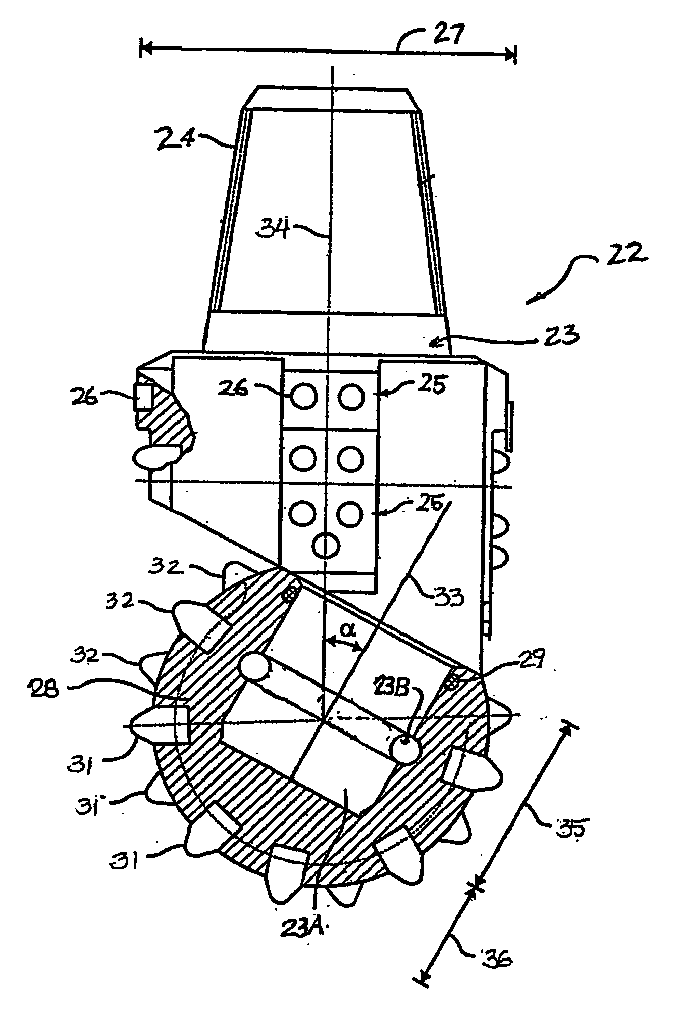
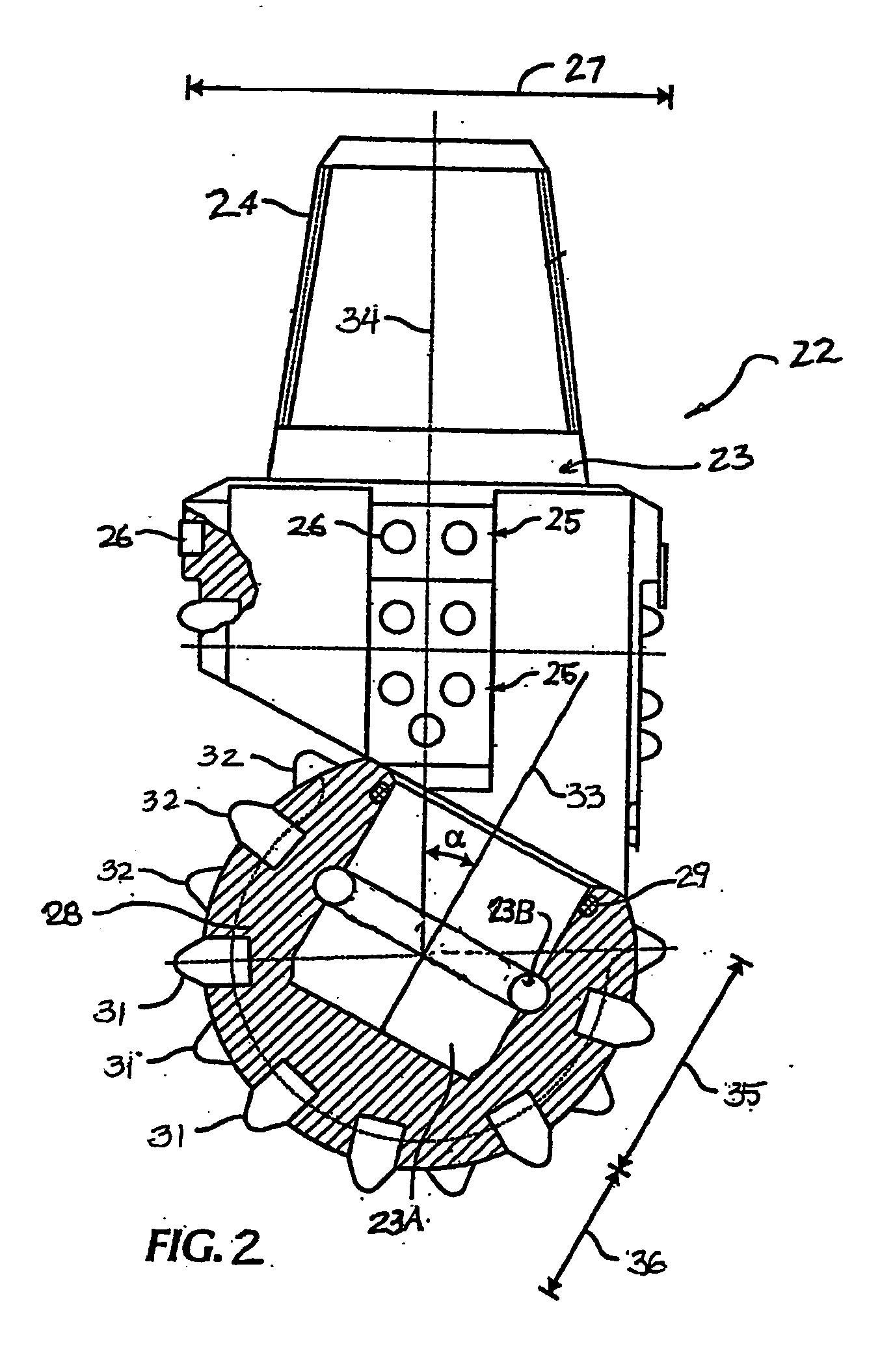
[0025] A general structure for a single cone roller cone drill bit which can be made according to various embodiments of the invention is shown in a cut away view in FIG. 2. The bit 22 includes a body 23 made of steel or other high strength material. The body 23 includes a coupling 24 at one end adapted to join the bit body 23 to a drill string (not shown) for rotating the bit 22 during drilling. The bit body 23 may also include gage protection pads 25 at circumferentially spaced apart positions about the bit body 23. The gage protection pads 25 may include gage protection inserts 26 in some embodiments. The gage protection pads 25 if used, extend to a drill diameter 27 of the bit 22.

[0026] Another end of the bit body 23 includes a bearing journal 23A to which a single roller cone 28 is rotatably mounted. In some embodiments, the cone 28 may be locked onto the journal 23A by locking balls 23B disposed in the corresponding grooves on the outer surface of the journal 23A and the inte...


PUM


Abstract

A roller cone drill bit is disclosed which includes a bit body adapted to be coupled to a drill string. A bearing journal depends from the bit body. A single roller cone is rotatably attached to the bearing journal. The roller cone is formed from steel and includes a plurality of cutting elements disposed at selected positions about the cone. At least one of the cutting elements has an extending body which has a first end coupled to the roller cone and a distal end extending away from the cone. The extending body is formed from steel. A super hard element is coupled to the distal end of the extending body to form a super hard cutting face for the cutting element.

Description

CROSS-REFERENCE TO RELATED APPLICATIONS [0001] This application claims the benefit under 35 U.S.C. §119(e) of U.S. Provisional Patent Application No. 60 / 538,745 filed on Jan. 23, 2004, titled “Cutting Structure for Single Roller Cone Drill Bit,” which is now incorporated by reference.STATEMENT REGARDING FEDERALLY SPONSORED RESEARCH OR DEVELOPMENT [0002] Not applicable. BACKGROUND OF THE INVENTION [0003] 1. Field of the Invention [0004] The invention relates generally to the field of roller cone (“rock”) bits used to drill wellbores through earth formations. More specifically, the invention is related to the structure of cutting elements used in roller cone bits having a single roller cone. [0005] 2. Background Art [0006] Roller cone drill bits are commonly used in the oil and gas industry to drill well bores through earth formations. One example of a conventional drilling system used to drill a well bore is shown in FIG. 1. The drilling system includes a drilling rig 10 used to turn...

Claims


Application Information

Patent Timeline
IPC IPC(8): E21B10/08E21B10/16
CPCE21B10/16
Inventor WITMAN, GEORGE B. IVYONG, ZHOU
Owner SMITH INT INC
Why Eureka
Try Eureka