

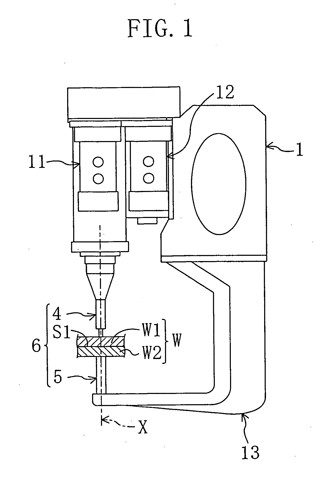
Friction spot joint structure
a friction spot and joint technology, applied in non-electric welding apparatus, manufacturing tools, welding/soldering/cutting articles, etc., can solve the problems of difficult adjustment, large time period, and unsuitable light metals such as aluminum and the like for fused joints such as arc welding, so as to achieve constant target joint strength and increase shear fracture strength. , the effect of easy adjustmen
- Summary
- Abstract
- Description
- Claims
- Application Information
AI Technical Summary
Benefits of technology
Problems solved by technology
Method used
Image

Examples
modified example of embodiment
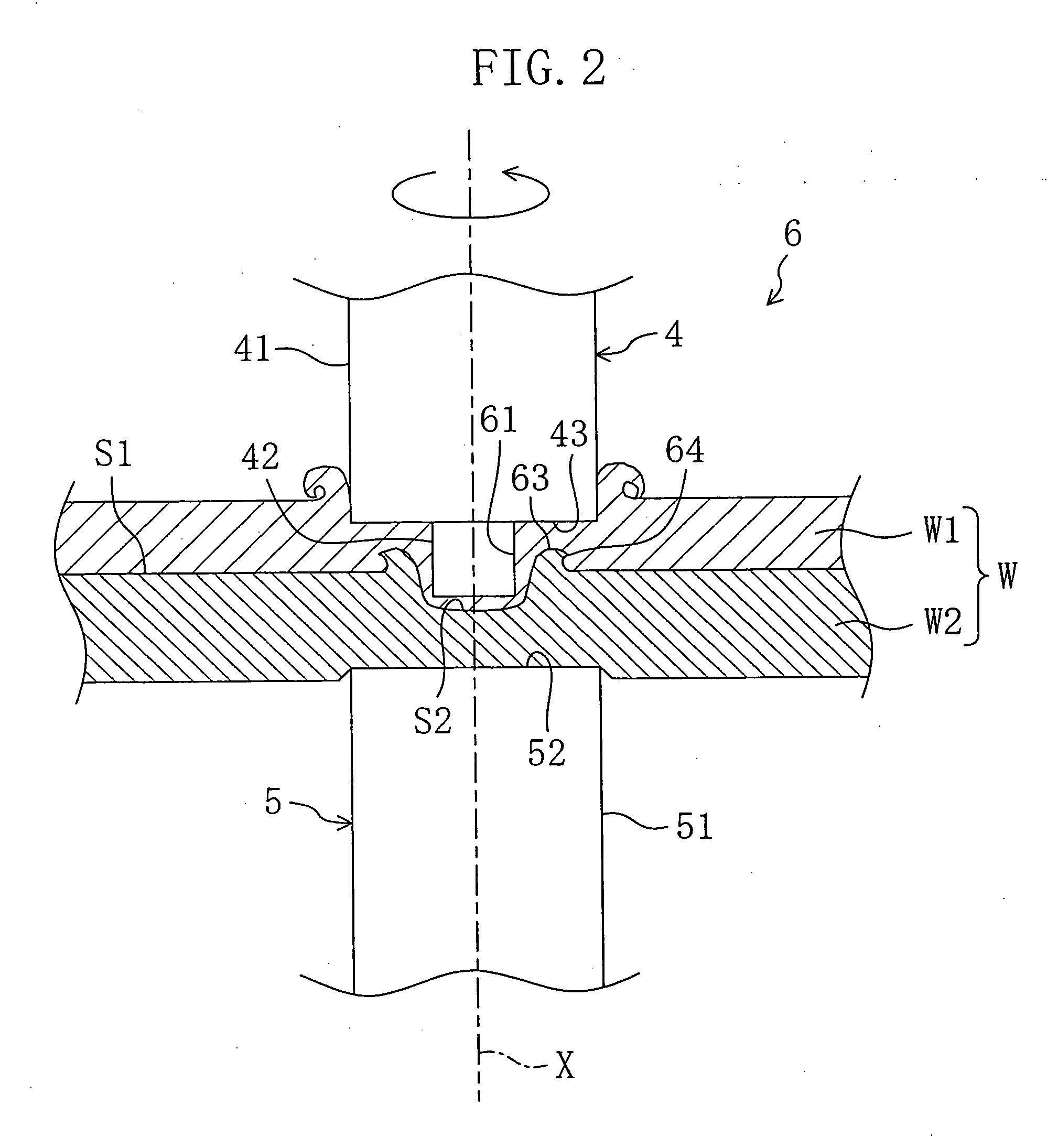
[0038] The receiving member 5 is fixed in the above embodiment but may be movable in the rotation axis X. Further, the receiving member 5 is formed of the column shaped main body 51 having the top face 52 of which shape and area are substantially the same as or larger than those of the tip end portion 41 of the rotary tool 4 in the present invention, but the receiving member 5 may be in a plate shape.
working examples
[0039] Working Examples that were performed practically will be described next.
working example 1
[0040] Referring to the work W, a 6000 series aluminum alloy of 1 mm in thickness was used as the first plate member W1 and a 3000 series aluminum alloy of 1 mm in thickness was used as the second plate member W2. The work W was joined using the aforementioned friction point joining apparatus.
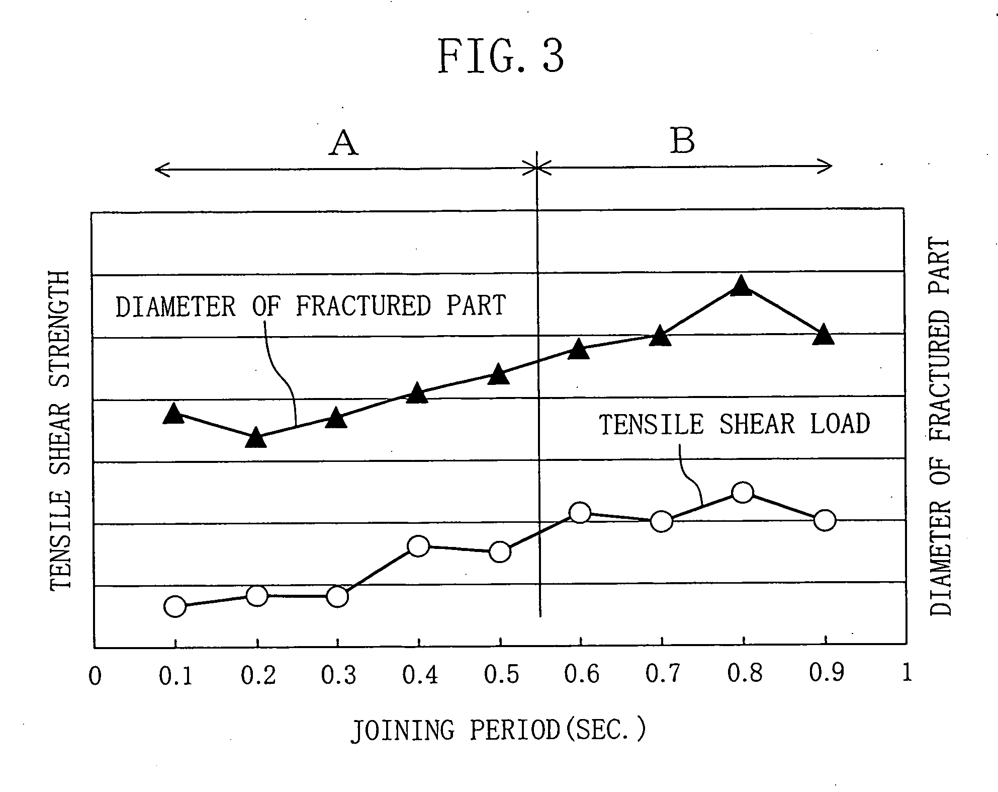
[0041] Specifically, the rotary tool 4 having the shoulder portion 43 of 8 mm in diameter was used, the pressure and number of rotation thereof were set to 3.42 kN and 2500 rpm, respectively, and a plurality of joint parts were formed in a single work W with the joining period changed per 0.1 sec. Then, the work W was cut into joint parts per joining period to observe each section thereof Further, the tensile shear strength of each joint part per joining period was measured.
[0042]FIG. 3 shows studied results of dependencies of diameters R of fractured parts and tensile shear strength on the joining period. FIG. 4 is a section showing the joint part obtained at the joining period of 0.4 sec., ...
PUM
| Property | Measurement | Unit |
|---|---|---|
| Time | aaaaa | aaaaa |
| Flow rate | aaaaa | aaaaa |
Abstract
Description
Claims
Application Information