RFID tag and its manufacturing method

a technology of rfid tags and manufacturing methods, applied in the direction of loop antennas with ferromagnetic cores, burglar alarm mechanical actuation, instruments, etc., can solve the problems of reducing cost, limiting the increase of manufacturing efficiency, and limiting the efficiency of manufacturing, so as to reduce the cost and size, and reduce the effect of fluctuations

Inactive Publication Date: 2005-08-18
FURUKAWA ELECTRIC CO LTD
View PDF4 Cites 81 Cited by
  • Summary
  • Abstract
  • Description
  • Claims
  • Application Information

AI Technical Summary

Benefits of technology

[0009] It is an object of the present invention to provide an RFID tag enabling efficient manufacturing thereof, an efficient manufacturing method of an RFID tag, and an RFID tag enabling effective measures against fluctuations of frequency characteristics to be carried out without resulting in increases in cost and size.

Problems solved by technology

However, the conventional RFID tags have following problems in terms of efficient manufacturing.
In other words, in the RFID as described in patent document 1, in winding the conductive material around the magnetic core, the winding speed is not increased when the magnetic core is a flat plate, and there are limitations in increasing the productivity, resulting in an obstacle to cost reduction in a recent situation where thinning of RFID tags is requested.
Further, in the RFID as described in JP2002-117383, it is necessary to suck the FPC with a vacuum suction apparatus when inserting the plane-shaped magnetic cores into the slits, a large-scale apparatus is required for the manufacturing, and there are limitations in increasing efficiency of the manufacturing.
Furthermore, when an RFID tag is attached to a metal article to use, there arises a problem that frequency characteristics fluctuate due to the interaction between the metal article and the antenna coil.
As measures against the fluctuations of the frequency characteristics, it is considered to place a metal plate for shielding inside the FRID tag, but the size of the RFID tag increases, while the cost is also increased, and in these respects, there are significant disadvantages.

Method used


Image

  • RFID tag and its manufacturing method
  • RFID tag and its manufacturing method
  • RFID tag and its manufacturing method

Examples


first embodiment

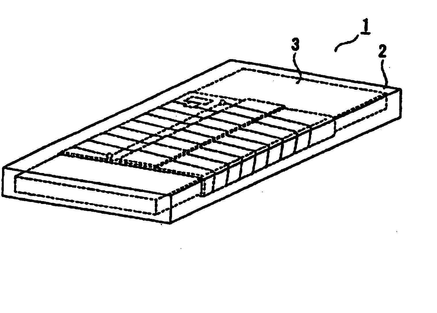
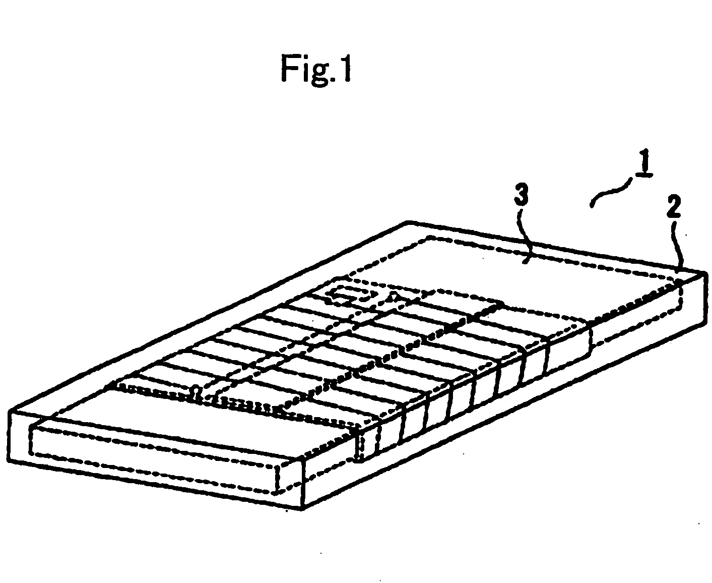
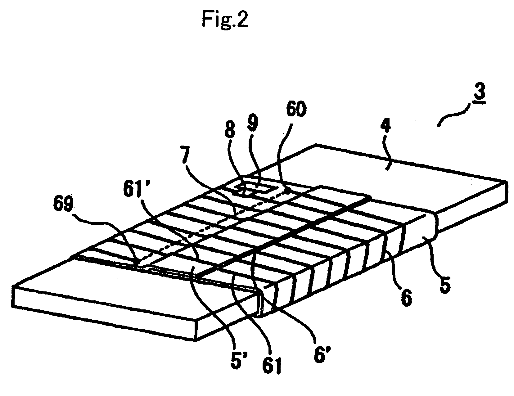
[0067]FIG. 2 is a view showing a structure of the transmitter / receiver 3 of the RFID tag 1 according to the As shown in FIG. 2, the transmitter / receiver 3 has the structure such that an FPC 5 is wound around a magnetic core 4 such as ferrite, ferrite-contained resin, and amorphous sheet. In addition, as the magnetic core 4, it is preferable to use a material having the flexibility such as the ferrite-contained resin and amorphous sheet to prevent the member 4 from cracking.

[0068] The FPC 5 is, for example, obtained by forming a resin such as PET, PI, PEN and liquid crystal polymer into a sheet with a thickness of about 30 μm. Linear conductor patterns 6 and capacitor 9 are formed on one side of the FPC 5, and to the linear conductor pattern 6 is connected an IC 8 which is bonded on the FPC 5 with an epoxy based adhesive or the like. Further, on the other side of the FPC 5 is formed a crossover pattern 7 that is connected to end portions 60 and 69 of linear conductor patterns 6 whic...

second embodiment

[0088] As described later, the shield conductor pattern 20 is not limited to the shape as shown in FIG. 12, and may be formed in various shapes. The second embodiment is characterized in that the shield conductor pattern 20 is formed on the side (back side) different from the side of the FPC 15 on which the linear conductor patterns 16 are formed. As described above, since the shield conductor pattern 20 is provided to reduce effects exerted on the coil-shaped antenna when the external attachment-target object approaches, it is necessary not to provide electrical connection between the linear conductor patterns 16, crossover pattern 17, IC 18 and capacitor 19 constituting the coil-shaped antenna and the shield conductor pattern 20.

[0089]FIG. 12 shows a cross sectional view of the structure of the transmitter / receiver 13 with the FPC 15 as shown in FIG. 11 wound around the magnetic core 14. In FIG. 12, the magnetic core 14 is disposed in the center, the linear conductor pattern 16 fo...


PUM

PropertyMeasurementUnit
thicknessaaaaaaaaaa
magneticaaaaaaaaaa
electricallyaaaaaaaaaa

Abstract

An RFID tag which is provided with a coil-shaped antenna such that a conductor is placed on the periphery of a magnetic core, the RFID comprising: the magnetic core, an FPC wound on the periphery of the magnetic core, two or more linear conductor patterns formed in parallel with one another on the FPC, an IC that is connected to the linear conductor patterns and disposed on the FPC, a crossover pattern that electrically connects one end and the other end of outermost linear conductor patterns among the linear conductor patterns formed in parallel with one another, where in the two or more linear conductor patterns, adjacent linear conductor patterns in a joint portion in the wound FPC are electrically connected in respective start edges and end edges.

Description

BACKGROUND OF THE INVENTION [0001] 1. Field of the Invention [0002] The present invention relates to an RFID (Radio Frequency Identification) tag which is a tag for use in article management, etc. provided with an antenna for transmission and reception and an IC chip for signal write and read and its manufacturing method. [0003] 2. Related Art [0004] RFID tags have been used conventionally in article management, etc. Each of the RFID tags is provided with an antenna coil and elements such as an IC connected to the antenna coil, activated by receiving a signal with a predetermined frequency transmitted from an interrogator in the antenna coil, thereby driving the elements such as an IC, communicates with the interrogator, and carries out article management or the like by reading data stored in the IC element, while writing new data in the IC element. The RFID tag are generally attached to a surface of an article to use, and as a structure of the antenna coil to stabilize frequency ch...

Claims


Application Information

Patent Timeline
Patent Type & Authority Applications(United States)
IPC IPC(8): G06K19/04G06K19/077H01Q1/22H01Q7/00H01Q7/06H05K1/00H05K1/16
CPCG06K19/041G06K19/0726G06K19/07749G06K19/07758G06K19/07771G06K19/07779Y10T29/49117H01Q1/22H01Q1/2225H01Q7/00H01Q7/06H05K1/0393H05K1/165G06K19/07781
Inventor SHOJI, NORIYUKIMAENO, KOICHIIEGAKI, MASATAKA
Owner FURUKAWA ELECTRIC CO LTD
Why Eureka
Try Eureka