
Inkjet head manufacturing method and inkjet head

a manufacturing method and inkjet head technology, applied in the field of inkjet head manufacturing method and inkjet head, can solve the problems of inability to detect abnormalities, useless parts cost, and inability to grasp piezoelectric characteristics well only by eigenfrequency, so as to save parts and useless manufacturing cost, easy detection, and high accuracy

Inactive Publication Date: 2005-08-18
BROTHER KOGYO KK
View PDF13 Cites 13 Cited by
  • Summary
  • Abstract
  • Description
  • Claims
  • Application Information

AI Technical Summary

Benefits of technology

The invention provides a method for manufacturing an inkjet head that can detect abnormalities in the piezoelectric characteristic of the piezoelectric element with high accuracy without ejecting ink. This is achieved by measuring the frequency characteristic of impedance of the piezoelectric structure of the bonded structure and determining whether or not it is a good product based on the distribution of the differences. This method can save a useless cost of parts and manufacturing costs for defective inkjet heads.

Problems solved by technology

However, the piezoelectric characteristic of the piezoelectric element cannot be grasped well only by the eigenfrequency.
Accordingly, when there is an abnormality in the piezoelectric characteristic of the piezoelectric element, the abnormality cannot be detected without ejecting ink from an inkjet head, which has been assembled.
It is therefore necessary to cause a useless cost of parts and a useless manufacturing cost for a defective inkjet head.

Method used


Image

  • Inkjet head manufacturing method and inkjet head
  • Inkjet head manufacturing method and inkjet head
  • Inkjet head manufacturing method and inkjet head

Examples


Embodiment Construction

[0023] A preferred embodiment of the invention will be descried below with reference to the drawings.

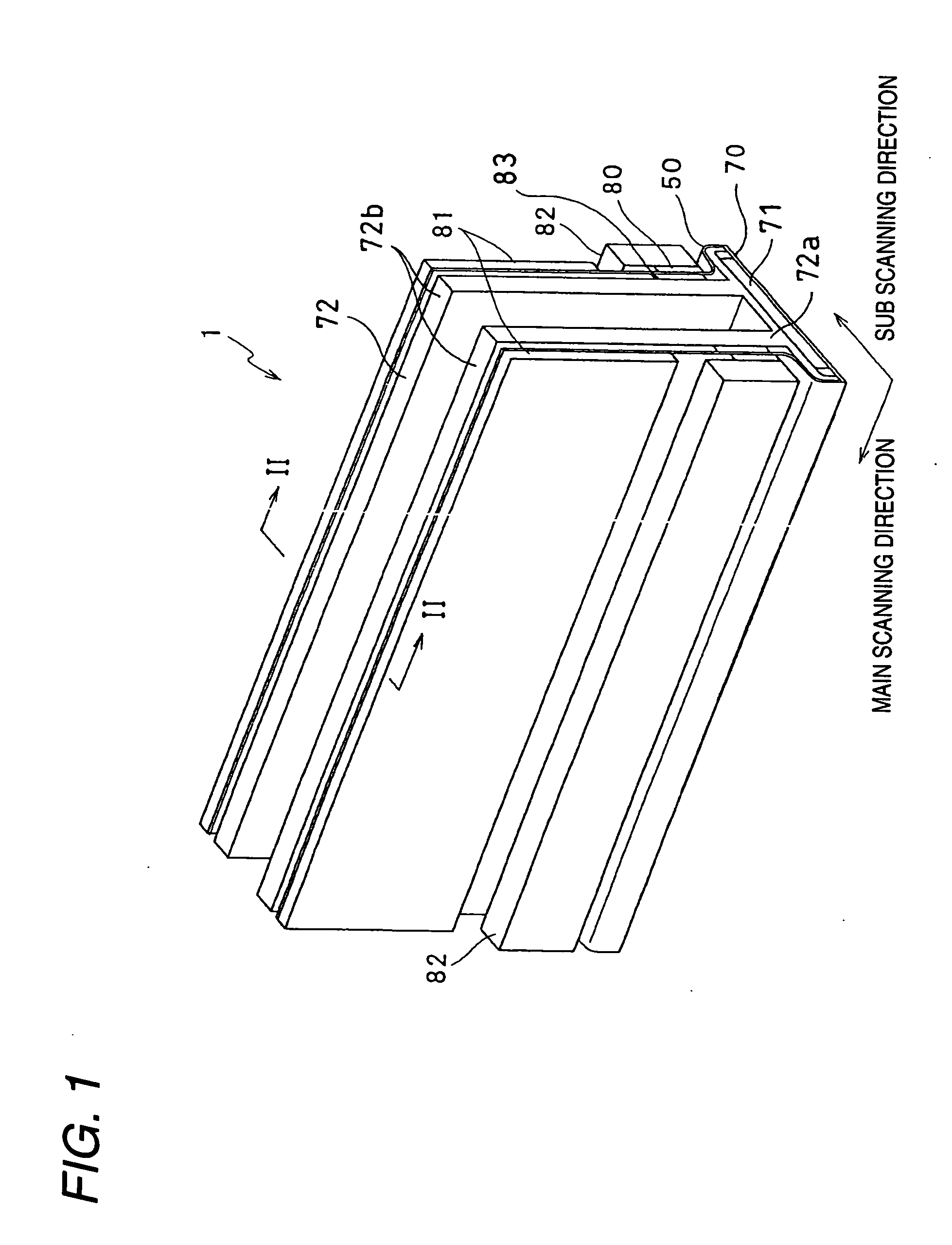
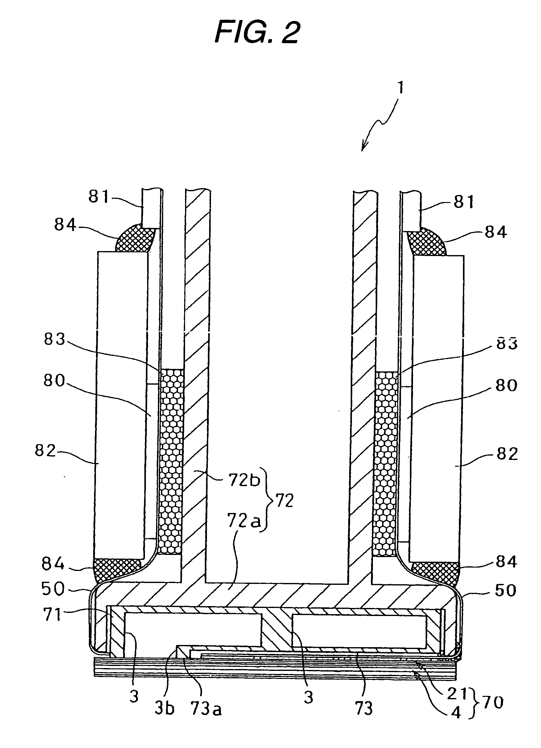
[0024] Description will be made about an inkjet head manufactured in a manufacturing method according to an embodiment of the invention. FIG. 1 is a perspective view of an inkjet head 1 according to this embodiment. FIG. 2 is a sectional view taken on line II-II in FIG. 1. The inkjet head 1 has a head body 70 for ejecting ink onto a paper, and a base block 71 disposed above the head body 70. The head body 70 has a rectangular planar shape extending in a main scanning direction. The base block 71 is a reservoir unit in which two ink reservoirs 3 are formed. The ink reservoirs 3 serve as ink flow paths through which ink is supplied to the head body 70.

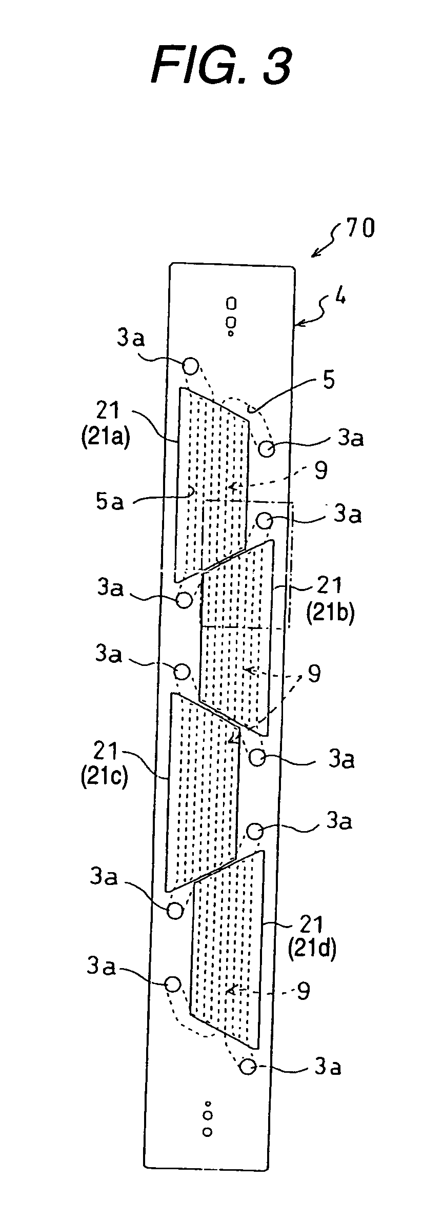
[0025] The head body 70 includes a flow path unit 4 in which ink flow paths are formed, and a plurality of actuator units 21 bonded to the upper surface of the flow path unit 4 by an epoxy-based thermosetting adhesive agent. The flow pa...


PUM

PropertyMeasurementUnit
thicknessaaaaaaaaaa
thicknessaaaaaaaaaa
electromechanical coupling constant k31aaaaaaaaaa

Abstract

A method for manufacturing an inkjet head includes producing a flow path unit, producing an actuator unit, bonding the actuator unit with the flow path unit to produce a bonded structure; measuring a frequency characteristic of impedance of the piezoelectric structure of the bonded structure in each of regions facing at least one of the pressure chambers, and determining whether or not the bonded structure is a good product on a basis of at least one of a distribution of (Fa−Fr) in the plural regions where Fa represents antiresonance frequency of each region at which impedance of each region are maximal and Fr represents resonance frequency of each region at which impedance of each region is minimal, a distribution of Fr in the plural regions, and a distribution of Zr in the plural regions, where Zr represents impedance of each region at the resonance frequency of each region.

Description

BACKGROUND OF THE INVENTION [0001] 1. Field of the Invention [0002] The present invention relates to a method for manufacturing an inkjet head in an inkjet printer for ejecting ink to thereby perform printing, and an inkjet head manufactured in the same method. [0003] 2. Description of the Related Art [0004] An inkjet printer has an inkjet head for ejecting ink onto a recording medium. There has been known an inkjet head including a plurality of pressure chambers supplied with ink, and a piezoelectric element corresponding to the pressure chambers, wherein voltage is applied to the piezoelectric elements so that the piezoelectric elements are driven to generate pressure in the pressure chambers and thereby eject ink from nozzles corresponding to the pressure chambers. Such an inkjet head is typically manufactured by bonding a flow-path member with a piezoelectric element. In the flow-path member, thin sheets of metal with openings formed therein are laminated to define pressure cham...

Claims


Application Information

Patent Timeline
Patent Type & Authority Applications(United States)
IPC IPC(8): B41J2/14B41J2/16
CPCB41J2/1609B41J2/1623B41J2002/14225B41J2002/14258B41J2002/14306B41J2002/14459Y10T29/49401B41J2202/20Y10T29/49128Y10T29/42Y10T29/49126Y10T29/4913B41J2002/14491
Inventor HIROTA, ATSUSHIISHIKURA, SHIN
Owner BROTHER KOGYO KK
Learn More